*Just a quick note on this apparently the 05 model engines are slightly different configaration and the EGR valve is mounted on top of the inlet manifold. The principle is still the same. Edited 16/2/11*
Background.
Recently I had my truck (2008 D4D Manual D/C Hilux 120,000kms) at the Toyota delaers in relation to an injector problem. I conversation the workshop foreman mentioned that they had recently cleaned the EGR and Intake systems of a number trucks with similar kms to mine. They had found that the intakes were extremely clogged with soot build up from the EGR.
Just to qualify myself I worked at a Toyota dealership for several years in the mid 80s (giving my age away a bit) and have approximately 15 years experience in building and repairing inboard ski boats. I no longer work in the mechanical repair industry but I have considerable experience in mechanical repairs. My Hilux was my first experience with a common rail diesel engine.
I decided to dismantle and clean the Intake system in my truck. Once I had removed the throttle body and EGR valve I discovered that the EGR valve was approximately 50% clogged and there was up to 10mm of soot build up on the elbow that connects the Throttle body/EGR to the intake manifold.
Photos of intake system
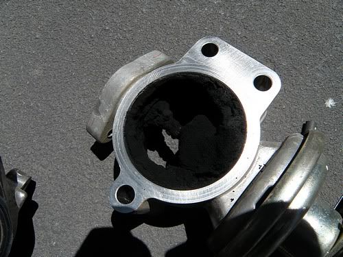
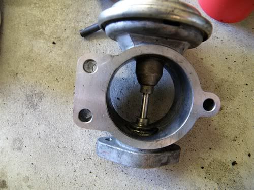
Clogged EGR
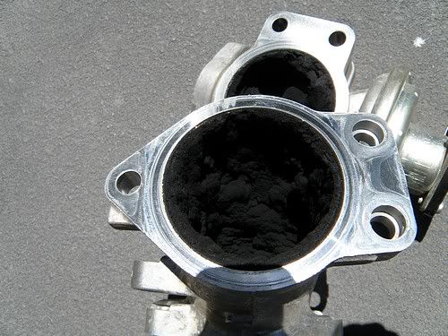
Clogged Elbow
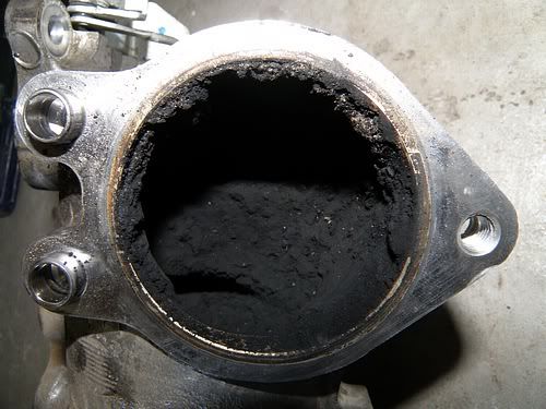
Clogged Throttle body
Top of inlet manifold
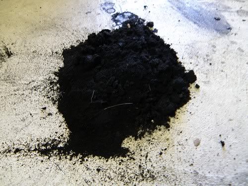
Soot from EGR and manifold
Clean EGR
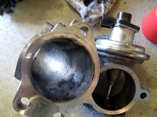
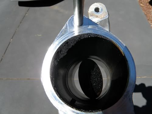
Clean elbow
Since cleaning out the intake system the difference in performance is markedly different. The engine appears to have a lot more torque and to put it bluntly it is a rocket ship compared to what it was before the clean.
Some of the consequences of a blocked Intake/EGR:-
• Starting problems
• Irregular idle
• Lack in acceleration
• Loss of power
• Increased fuel consumption
• Higher exhaust emissions
• EGR system failure warning
(Taken from Wynns EGR 3 product information sheet)
I have compiled this ‘How to’ on dismantling and cleaning the intake system to assist other newhilux.net members. The process is fairly time consuming and would have a high labour value if done at a workshop. I have tried to make the instructions as detailed as possible but since I was doing it from memory I may have left a couple things out. (Please let me know if there is anything missing and I will add it) I believe that this should be able to be done by a person with basic to medium level of mechanical repair as most of the procedure is simply dismantling and reassembling. However if you don’t feel confident in doing it, it would probably be better to get it done by someone who is competent.
The process for dismantling the intake system is not that complicated if only the Throttle body and EGR are removed and only requires a normal set of tools. Removing the intake manifold is more complicated as the injection pipes need to be removed and re-tensioned when replaced using a crowfoot spanner and tension wrench.
Tools:-
3/8”-1/2” drive metric socket set
Metric open end-ring spanners
Screwdriver set
Tension wrench
17mm crowfoot pipe spanner

Can of Throttle Body/Carby Cleaner

Assortment of small wire/tooth brushes, rags and blanking off items.
Tips.
1. Take your time.
2. Try to have the vehicle cold when you start work on it.
3. Take a number of photographs of the engine/intake system during the process before you dismantle anything.
4. If you remove any fuel hose make sure the ends are plugged. The shank of a drill bit makes a good plug.
5. If you remove any of the injection pipes make sure all of the ports are blanked off. Place the pipes in a plastic bag and write the pipe number on the bag.
6. Use a vacuum cleaner to suck up bits of debris rather than compressed air to blow debris away.
7. Reconnect wiring plus and hoses as you reassemble components.
8. All of the gaskets in the intake system are steel with a coating and are able to be reused so long as you are careful when they are being removed.
9. The majority of bolts are screwed into aluminium so while they need to be tightened don’t over do it.
10. When re-assembling make sure that everything fits together neatly don’t try to force things by clamping together with bolts.
Stage 1 – Removing the Throttle Body and EGR valve.
1. Disconnect the negative lead on the battery (wait 90 secs after turning key off, don’t want to have any airbag mishaps) Optional to totally remove battery as it gives more room to work.
2. Remove the cover from the intercooler at the top of the engine. (10mm bolt heads)
3. Remove the two wiring plugs from the passenger side of the intercooler (there is a clip on the side of the plug that must be depressed to pull the plug out). No.2 on Fig 1.
4. Using a pair of pointy nosed pliers (or similar) depress the tabs on either side of the clip that holds the wiring loom to the intercooler tube. No.3 on Fig 1
5. Disconnect the plastic vacuum that connects to the EGR valve. No.4 on Fig 1
6. Loosen the clamps that hold the rubber tubes onto the throttle body and turbo charger. No.5 on Fig 1
7. Remove the four bolts that hold the intercooler to the engine. (12mm bolt head)
8. The intercooler (No.1 on Fig 1)should now feel free of the brackets. Firstly remove the hose from the throttle body by gently pulling the passenger side of the intercooler assembly to the front of the vehicle (it may be necessary to break the seal between the hose and pipe by placing a flat bladed screw driver between the pipe and hose a number of times)
9. Lift up the intercooler pipe on the turbo side. The intercooler assembly should now be able to be removed from the vehicle. (check that there is still no wiring or hoses connected before trying to remove same)
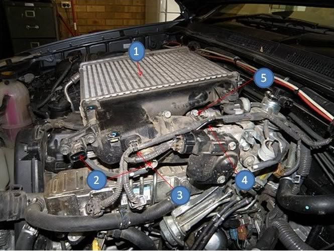
Fig 1
10. Remove the wiring plugs from the throttle body servo, EGR valve and the throttle position switch. (No 1 Fig 2 & 3)
11. Remove the vacuum tube from the EGR valve. (No2 on Fig 2)
12. On the passenger side of the throttle body/EGR there is a bracket with modules attached. The bracket is attached to the throttle body/EGR with three bolts (12mm heads). A vacuum valve will be required to be removed from a clip access one of the bolts. (No.5 on Fig 2) Remove the three bolts and the bracket will be able to be moved away from the assembly. (No.3 on Fig 2) It will still have vacuum tubes attached, leave the tubes attached and let hang down.
13. At the rear of the EGR valve there are two bolts (12mm heads) attaching a water pipe to the rear of the EGR. Remove the bolts so the pipe is free of the EGR. (No.4 on Fig 2 & 3)

Fig 2
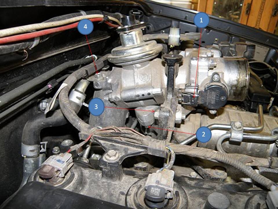
Fig 3
14. Remove the two bolts (10mm heads) that connect the EGR Heat exchanger to the EGR valve. (No.2 on Fig 3)
15. Remove the bolt (12mm head) that connects the supporting bracket to the throttle body (No.3 on Fig 3)
16. Remove the 3 bolts (12mm heads) that connect the EGR elbow to the top of the inlet manifold. (No.1 on Fig 4)
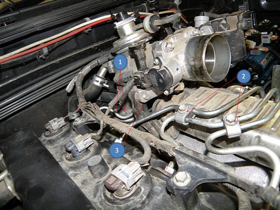
Fig 4
17. The throttle body and EGR assembly should now be loose and able to be removed from the engine.
18. Once the assembly has been removed carefully remove the steel gaskets from the inlet manifold and EGR inlet.
19. Inspect the assembly to determine how much build up of soot there is inside EGR and elbow. If there is no or minimal build up it may be possible to clean the assembly as a complete unit.
20. If there is a large amount of soot in the assembly remove the 3 nuts (12mm) that connect the elbow to the EGR valve. Once undone the throttle body, EGR valve and elbow should separate. Carefully remove the gaskets.
21. Depending on the type of build up it may be possible to remove the majority of the soot with a toothbrush or small wire brush. (I found in mine that near the throttle body was soaked in oil and I had to scrape it out)
22. Once the majority of soot/oil is removed a spray with Throttle Body/Carby Cleaner and a final scrub should remove the remaining soot/oil.
Note:- At this point you should be able to determine whether or not the intake will need to be removed for cleaning. I noted with mine that the majority of the soot build up was around the inlet of the intake and No.4 intake port. The soot was easily removed with a small wire brush and using a vacuum cleaner the loosened soot would be able to be sucked out. The remaining soot build up would be able to be cleaned by giving a clean with Wynns EGR3 cleaner (discussed later) after the intake was reassembled.
‘Axeten’ found that when he had removed the Throttle Body/EGR assembly that the intake was coated in a build up of soot and oil. He decided to remove the inlet manifold to properly clean the manifold and intake ports.
23. Reassemble the Throttle body, EGR and elbow. Make sure that the vacuum canister on the EGR is pointing up. Ensure that all mating surfaces are clean before reassembly.
24. Reassemble the intake system if not removing the intake manifold.
Stage 2 – Removal of the inlet manifold.
I found that it was easier to access a lot of the bolts if I removed the fuel filter assembly and oil filter. Block the fuel hoses from the fuel filter and outlets of the filter, remove wiring plugs. Cover the oil filter area on the block with a clean rag.
1. Remove the clamps from the injector pipes.(No.2 on Fig 4)
2. Remove the clamp between the oil dipstick tube and main feed pipe from the injector pump.
3. Remove the bolt (12mm head) that bolts the dipstick tube to the inlet manifold. The tube should now be able to be swung back out of the way (easier than removing it entirely)
4. Remove the top bolt (12mm head) on the support stay that runs between the inlet manifold and block.
5. Remove the bottom bolt (12mm head) on the support stay. Leave the wiring and hoses attached but disconnect the vacuum hose that runs to the block. You should be able to pull it back out of the way.
6. Loosen the cap on the coolant bottle to relieve pressure. Disconnect the two coolant hoses that connect to the EGR heat exchanger. Remove one at a time and plug immediately. This should prevent excessive coolant loss. (No.6 on Fig 2)
7. Start removing the injector pipes. (Caution- before loosening any of the pipes put on a pair of goggles on the slim chance that there is still pressure in the fuel rail and diesel squirts from one of the connections. The injection system runs at between 20,000 and 30,000 psi) To loosen the nuts on the pipes use a 17mm crowfoot pipe spanner (a pipe spanner that connects to your 3/8” – ½” drive extension bar). (You probably could get away with loosening the nuts with an open ender but you are going to need the crowfoot spanner the tension the nuts later on) Loosen the top and bottom nuts on No.1 injector pipe. Once totally undone remove the pipe and place in a plastic bag marked No.1. Blank off the thread ends at the injector and fuel rail. Repeat the process from No.2 thru to No.4.
8. Remove the EGR heat exchanger. There is one bolt (12 mm head) that connects the exchanger to the manifold on the side. The exchanger is connected to the front of the head under the thermostat housing with nuts (10mm). Remove bolt and nuts and the exchanger should be able to be removed.
9. Remove the intercooler and manifold support bracket at the top of the engine.(No.3 on Fig 4)
10. Remove the bar that connects the glow plugs. Unscrew the white plastic caps with fingers. Undo nuts (10mm) on glow plugs. At the rear of the bar there is a wire connected. Hold onto the connector and loosen nut (should stop the bar from bending while your trying to undo the nut).
11. Remove the fuel return pipe. Return pipe runs from the rear of the cylinder head, across the inlet manifold and underneath, to the front of the engine. Disconnect the two hoses attached to the pipe at the front of the engine and plug the hoses. Disconnect the hose that connect the pipe to the rear of the fuel rail. Remove the bolts (12mm heads) from the brackets that connect the pipe brackets to the manifold. At the rear of the cylinder head the return pipe is attached using a banjo connection with a 12mm head. Loosen the banjo bolt being careful not fully remove the bolt from the pipe otherwise the sealing washers may drop out. Remove the pipe and bolt as one unit.
12. Remove the two bolts (10mm heads) that hold the insulation under the inlet manifold. Pull the insulation out and this allows access to the manifold bolts.
13. Remove the inlet manifold. There are four bolts and two nuts (12mm) (two bolts are located high up under the manifold) Loosen all of the bolts first before totally removing. Once the bolts/nuts are removed carefully remove the inlet manifold so as not to damage the gasket. Before the manifold can be totally removed disconnect the wiring plugs that connect to the fuel rail and the vacuum hoses connected to the servo at the rear of the manifold. (No.1 on Fig 5) Remove the gasket from the cylinder head.
14. Remove the insulation pad on top of the manifold.
15. Clean the build up soot/oil in the inlet manifold using a small wire brush and vacuum cleaner ( I was also able to clean a lot of the inlet ports in the cylinder head by the same method) Throttle Body/Carby cleaner also works pretty well in removing the deposits from the inlet manifold. (I wouldn’t spray it inside the head).
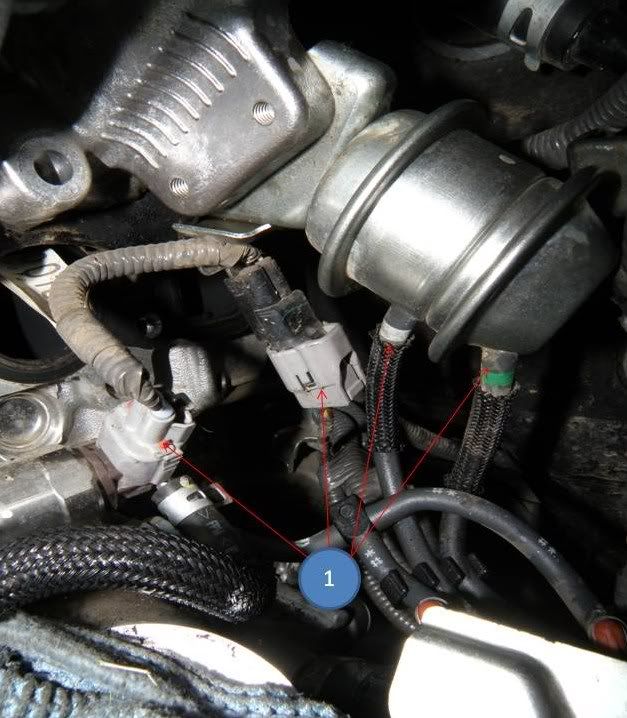
Fig 5
Reassembly
16. Once everything is clean time to reassemble and is basically the reverse disassembly with a couple of things to watch. Make sure all of the mating surfaces are clean.
17. Before fitting the inlet manifold place the insulation pad around the glow plugs. Clean insulation pad first.
18. Fit the gasket back onto the head and push the inlet manifold against the gasket ensuring the manifold mates up without any gaps. Remember to refit the wire connectors and vacuum hoses before sliding the manifold into place. Fit the bolts and do up finger tight and then tighten.
19. Fit the insulation under the manifold.
20. Refit the fuel return pipe and connect hoses.
21. Refit the bar that connects the glow plugs. Make sure that the connection at the rear of the inlet manifold is not touching any metallic part.
22. Refit the support bracket on top of the engine.
23. Refit the EGR heat exchanger but only do the bolts/nuts finger tight at this stage.
24. Fit the injector pipes starting at No.4 and working to No.1. Make sure that the connections are clean and place clean engine oil on the threads on the pipe nuts. Connect the top and bottom nuts and do up finger tight ensuring that the flares at the end of the pipes fit neatly into the unions. Using tension wrench torque to 26 ft.lbs. Refit pipe support clamps.
Note:- Toyota normally specify that the pipes should be replaced whenever they are removed. I considered this but because they were going back onto the same mating surfaces they should seal. I have also realised that when Toyota replaced my No.3 injector they would have had to remove all of the injector pipes anyway. They did not replace them and they have not leaked.
25. Refit the Throttle body and EGR vale assembly. Put gasket in place and position on top on inlet manifold ensuring that it has mated properly and fit bolts to finger tight. (Also don’t forget to fit the EGR gasket in place. Once in place tension bolts. The EGR heat exchanger should still be loose. Position so that heat exchanger fits neatly to the EGR valve and insert bolts with 10mm heads and tighten. Now tighten the 10mm nuts under the Thermo housing that attach the heat exchanger to the cylinder head. Tighten the mounting bracket bolt between the heat exchanger inlet manifold.
26. Continue to fit all of the remaining hoses, wiring connectors and brackets as per the reversal of the disassembly procedure. Do not fit the intercooler cover at this stage.
27. Once the engine is reassembled do a check that all connections are tight. Oil filter refitted and engine filled with oil if drained.
28. Turn key to on wait for a minute or so to start. It may take a couple of attempts to start vehicle as the fuel system will need to be purged.
29. Once engine has been running for a while visually check injector pipe connections for leaks (wear safety goggles)\
30. Once satisfied there are no leaks refit intercooler cover.
Preventative treatment for EGR.
After doing a bit of research I located a product made by Wynns called EGR3 aerosol –air intake, inlet valve and egr cleaner. The product is made mainly for workshop use and is not normally sold through retail outlets. I contacted the state sales rep who advised that I could buy the product through an Autobarn store. Part no. to quote is 23379. The instructions on how to use the product are contained in the product information sheet.
Here is a link to the Product Information Sheet
[urlhttp://www.wynns.net/product_files/Exhaust%20Gas%20Recirculation%203%2023379%20%20High%20Pressure%203%2012193%20PIS.pdf][/url]
I have used a can on my truck. I removed the top of the air cleaner and sprayed it directly into the hose to the turbo (as per instructions). Use an extension tube to spray past the MAF sensor. I wanted to clean out any remaining deposits in the intake system. As per photo
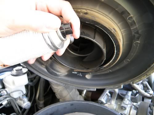
Using EGR3
The product was pretty simple to use and took about 20 minutes. I will be using it every time I change my oil as a preventative measure.
Written by
Steve B
Copyright 2011