Fridge/slide/power
49 posts
• Page 2 of 3 • 1, 2, 3
Re: Fridge/slide/power
![]() by Steve9R on Wed, 03 Feb 2010 7:32 +0000
by Steve9R on Wed, 03 Feb 2010 7:32 +0000
Yeah the tubs are earthed. I run my aux battery in the tub via a redarc in the engine bay and run fuse boxes etc for everything in the tub itself.. much better weight distribution as ive got it centered in the middle under the rear window, and ive made provision to allow me to put additional batteries next to it if i need to. i run a momentry switch to the redarc to link the two batteries to jump the primary if i need to, but otherwise ive got a Plasmatronics PL20 controller for my solar panels that i can hook up as well .. can never have too much power 
-

Steve9R - Valued Contributor
- Posts: 5248
- Joined: Wed, 11 Apr 2007 1:00 +0000
- Location: Melbourne, VIC
Re: Fridge/slide/power
![]() by rosco01 on Wed, 03 Feb 2010 10:02 +0000
by rosco01 on Wed, 03 Feb 2010 10:02 +0000
Thanks Pete and Steve,
Yes, I ran an additional 4 B&S from the chassis earth under the tub (originated from engine bay body/battery earth) up into the tub. I drilled through the tub and ground down to bare steel finally fitting M8 zinc plated bolt, nut, flat and spring washers. This is now my earth point for all tub equipment including Anderson and trailer sockets.
Hopefully will have pix up tonight...... should have shot the rear cable mounts grommets before plastering them with Sikaflex 221.... sorry, looks a bit "messy"..... but you'll get the picture (excuse pun).....
I used a front wheel bearing rubber seal for the rear most grommet - then fitted a blind plug into that.... this was necessary to get the conduit to make the sharp right hand bend upwards to the tub without threatening to split it..... or have the conduit/body wear through a standard grommet....
pix tonight......
frats,
Rosco
- rosco01
- Posts: 303
- Joined: Sun, 02 Aug 2009 8:21 +0000
Re: Fridge/slide/power
![]() by rosco01 on Wed, 03 Feb 2010 3:57 +0000
by rosco01 on Wed, 03 Feb 2010 3:57 +0000
Ok, this will be a biggie - more pix than words..... a bit repetitive - but should give anyone thinking about this a good look at alternatives.....
First pic is of the engine bay - you can see that I made up a distribution board and fitted it to the engine bay l/h skirt.
On this board, there are two 70A resettable circuit breakers. The one closest to the firewall is power supply lead to RanOx only.
The other one supplies the bus bar (lid removed).. this bus bar has 13 terminals - only two of which are being used at present... it affords ample supply to future needs.
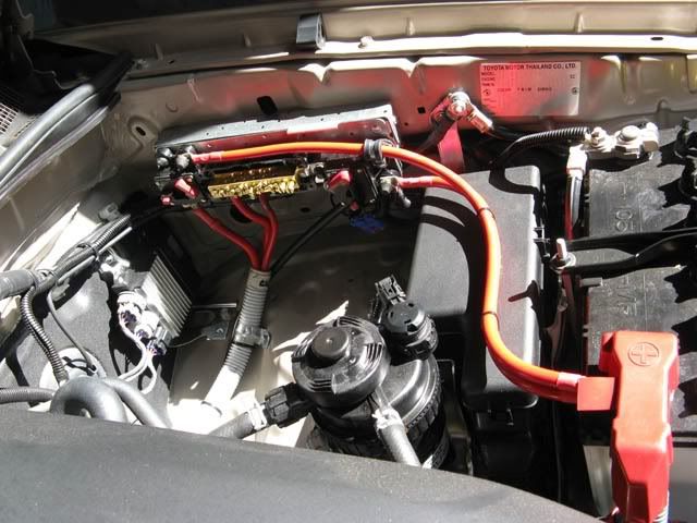
You can see that I have connected and run a 4 B&S black earth lead from the factory engine bay terminal. It was supposed to go down some larger (32 mm ) conduit - but that is now sitting "spare" in my shed.... I couldn't get it through the opening between the chassis and sub floor..... so, earth lead had to run tied to the 25 mm conduit used instead.....
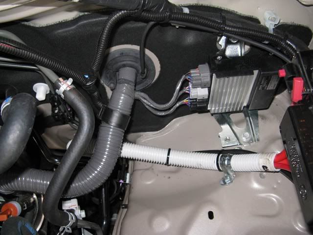
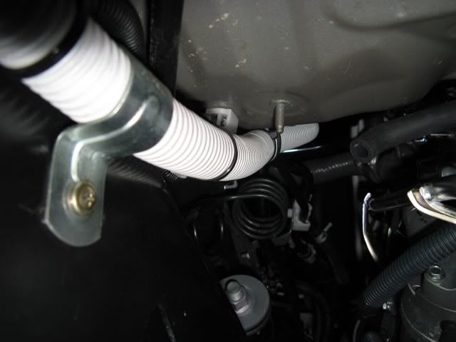
In the next pic, you can see that the three positive leads (two 4 B&S and one 6 B&S) run through the 25 mm conduit.
It is fixed to the wheel arch and further down to the toe-board. I took particular care to ensure that the conduit did not come into contact with any hoses, pipes or fittings as it passed to the sub-floor.
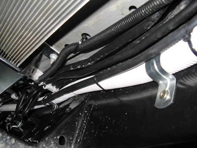
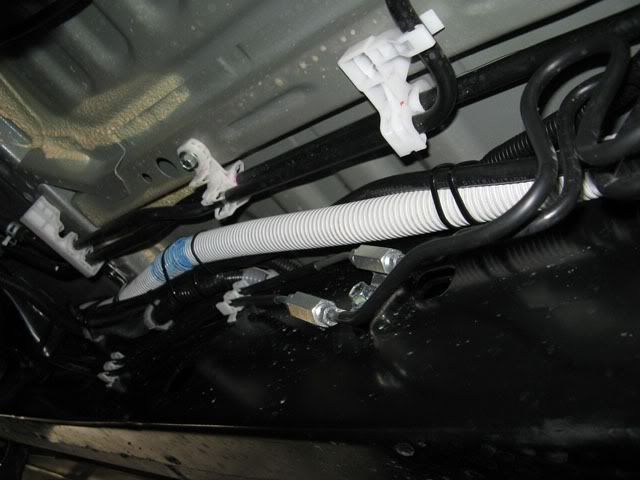
In the next pic, we go underneath and you can see that the conduit has been clamped in two further locations - by drilling a 3.5 mm hole into the chassis and mounting a bracket. The tapping bolt threads are coated with Loctite 262.
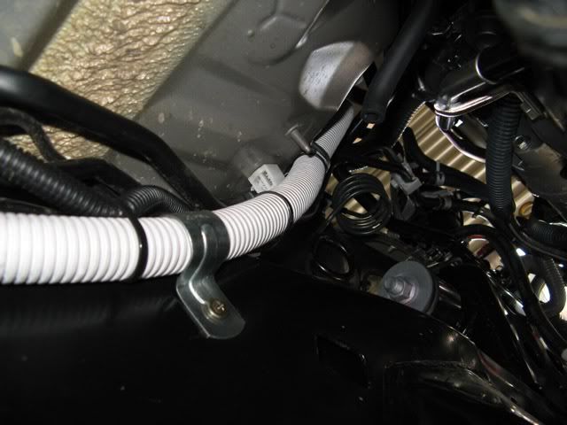
The next pic is just a bit more of how I managed to keep the conduit away from factory fittings.
and....
and
and
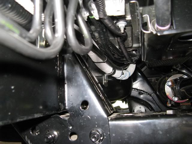
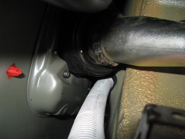
The next pic shows where I found the best place to cross over the chassis - there is a gap sufficient enough to pass 25 mm conduit over the chassis and not foul the sub-floor..... 32 mm would not pass through here....
another view..
from the rear...
When it comes out the other side, from above the chassis - there is a conveniently placed factory hole which it can pass through. This is in the side-step bracket. I used a rubber grommet here and later sealed them in place with Sikaflex 221....
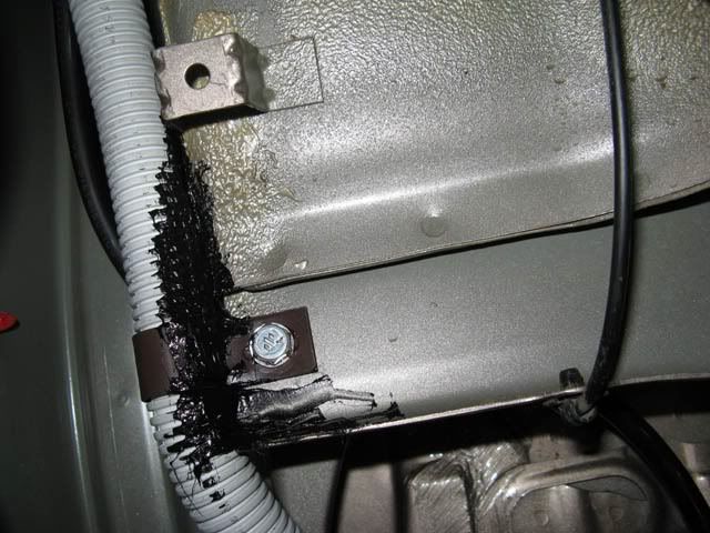
This pic is looking to the rear - you can see my first attempt at running the leads along this path by the grometted earth lead above.....
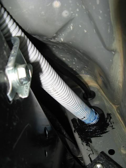
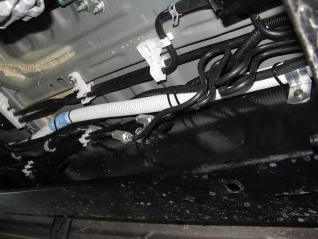
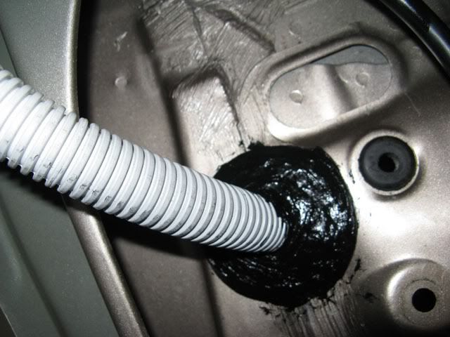
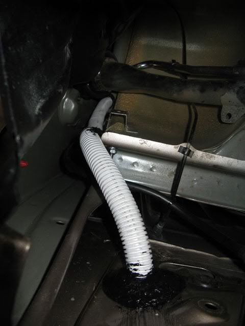
This next bit took me ages to decide to do - I had to drill out the rear of the lower body end - for the conduit to pass through on its way to the tub..... I can't tell you how many measurements I made before "biting the bullet".
The conduit passes through a Holden rubber wheel bearing inner seal - inside that is a drilled out rubber bayonet plug - all sealed (very messily) in place and secured with Sikaflex 221.
Please ignore the un-inhabited grommet - it was the remains of the first attempt to get earth lead to the chassis - I opted later to pass it higher and make chassis earth a lot closer to the body end wall...
Now it got tricky - I don't know if those who have a petrol engined version of our truck want to follow my lead here - I wouldn't have.....
I now had the dilemma of getting the conduit up and over the wheel arch - I posted up a question at some stage asking if anyone had removed the wheel-arch covers and how to do it .... sadly, I didn't get a response and had to "learn" that they are sandwiched between the flares and the body..... so, after another day - removed screws and plugs and just pulled away the cover to the rear as far as I could without stressing anything too much...
Once I got a peek inside the cavity, the best option I considered was to go up..... but could not get past the fuel filler area.
From inside the tub, I measured and found that there was just enough room to run the conduit up through the first "indented" area on the wall of the tub. The bottom angled section had sufficient area to pass grommet and conduit through.
I drilled out a hole for the earth lead from the chassis first - and had a good "feel" around for anything "hidden".... it was clear as far back as the filler assembly.
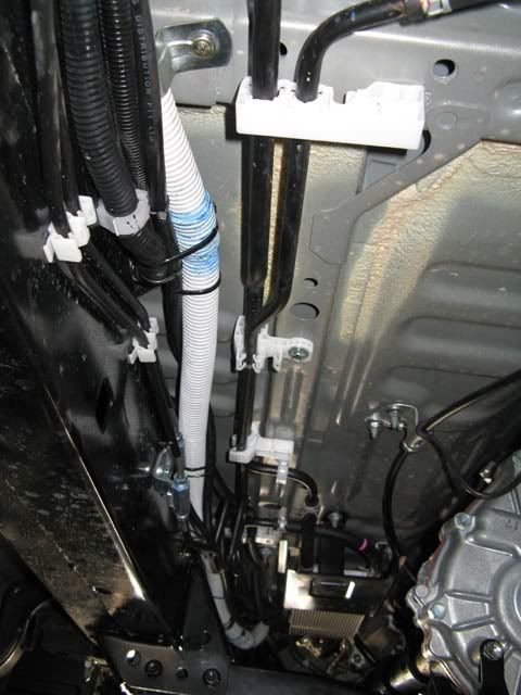
This pic taken from the rear looking forwards shows the conduit making it upward turn towards the filler assembly - this is all hidden by the wheel-arch cover....
I used a "D" clamp to fasten the conduit to the front of the tub - there is a great little plate there which is positioned just perfectly for this..... sorry about the Sikaflex.... should have shot pix of this and the hole in the end wall first....
The next pic shows where I found the best location to get into the tub - if I could have removed those covers - it probably would have been fortuitous to pass the conduit between the cover and wheel-arch then enter from behind the wheel arch.... but - I didn't want to destroy/damage the flares or cover.....
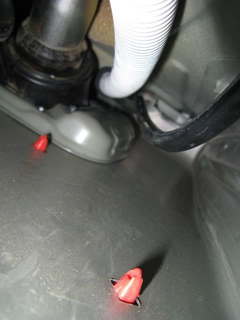
Final pic shows a little closer at where the conduit enters the tub - just away from the filler assembly.
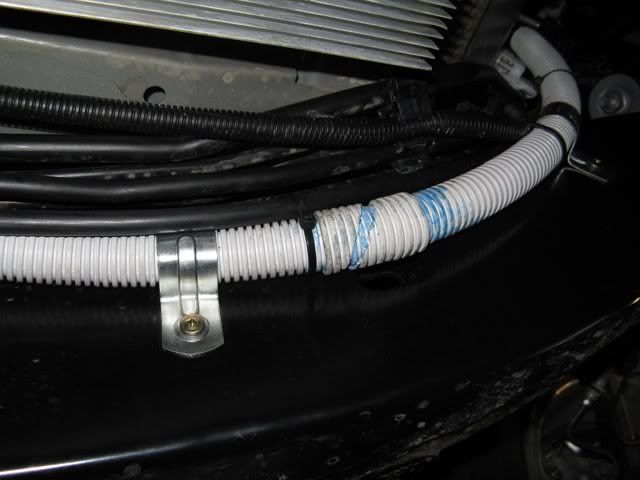
As you will have noticed, at four locations along the conduit - I had to "sleeve" it using binding - this was made at 850 mm intervals - and served also to further protect the conduit - at points where contact was made with the vehicle....
Stay tuned - I'm finished under the vehicle.
Where my leads now pass into the tub, they will be terminated and bolted (brass) through the distribution board.
Next installment will be the distribution board made from UHWPE (chopping board) .... it is completed and fitted through the two bolts which hold the canopy mount assembly onto the body.... I'll throw up some pix of what I did to achieve this later.....
I am about to map out the arrangement for componentry on this board.
Sorry for the 'novel"....
frats,
Rosco
First pic is of the engine bay - you can see that I made up a distribution board and fitted it to the engine bay l/h skirt.
On this board, there are two 70A resettable circuit breakers. The one closest to the firewall is power supply lead to RanOx only.
The other one supplies the bus bar (lid removed).. this bus bar has 13 terminals - only two of which are being used at present... it affords ample supply to future needs.
You can see that I have connected and run a 4 B&S black earth lead from the factory engine bay terminal. It was supposed to go down some larger (32 mm ) conduit - but that is now sitting "spare" in my shed.... I couldn't get it through the opening between the chassis and sub floor..... so, earth lead had to run tied to the 25 mm conduit used instead.....
In the next pic, you can see that the three positive leads (two 4 B&S and one 6 B&S) run through the 25 mm conduit.
It is fixed to the wheel arch and further down to the toe-board. I took particular care to ensure that the conduit did not come into contact with any hoses, pipes or fittings as it passed to the sub-floor.
In the next pic, we go underneath and you can see that the conduit has been clamped in two further locations - by drilling a 3.5 mm hole into the chassis and mounting a bracket. The tapping bolt threads are coated with Loctite 262.
The next pic is just a bit more of how I managed to keep the conduit away from factory fittings.
and....
and
and
The next pic shows where I found the best place to cross over the chassis - there is a gap sufficient enough to pass 25 mm conduit over the chassis and not foul the sub-floor..... 32 mm would not pass through here....
another view..
from the rear...
When it comes out the other side, from above the chassis - there is a conveniently placed factory hole which it can pass through. This is in the side-step bracket. I used a rubber grommet here and later sealed them in place with Sikaflex 221....
This pic is looking to the rear - you can see my first attempt at running the leads along this path by the grometted earth lead above.....
This next bit took me ages to decide to do - I had to drill out the rear of the lower body end - for the conduit to pass through on its way to the tub..... I can't tell you how many measurements I made before "biting the bullet".
The conduit passes through a Holden rubber wheel bearing inner seal - inside that is a drilled out rubber bayonet plug - all sealed (very messily) in place and secured with Sikaflex 221.
Please ignore the un-inhabited grommet - it was the remains of the first attempt to get earth lead to the chassis - I opted later to pass it higher and make chassis earth a lot closer to the body end wall...
Now it got tricky - I don't know if those who have a petrol engined version of our truck want to follow my lead here - I wouldn't have.....
I now had the dilemma of getting the conduit up and over the wheel arch - I posted up a question at some stage asking if anyone had removed the wheel-arch covers and how to do it .... sadly, I didn't get a response and had to "learn" that they are sandwiched between the flares and the body..... so, after another day - removed screws and plugs and just pulled away the cover to the rear as far as I could without stressing anything too much...
Once I got a peek inside the cavity, the best option I considered was to go up..... but could not get past the fuel filler area.
From inside the tub, I measured and found that there was just enough room to run the conduit up through the first "indented" area on the wall of the tub. The bottom angled section had sufficient area to pass grommet and conduit through.
I drilled out a hole for the earth lead from the chassis first - and had a good "feel" around for anything "hidden".... it was clear as far back as the filler assembly.
This pic taken from the rear looking forwards shows the conduit making it upward turn towards the filler assembly - this is all hidden by the wheel-arch cover....
I used a "D" clamp to fasten the conduit to the front of the tub - there is a great little plate there which is positioned just perfectly for this..... sorry about the Sikaflex.... should have shot pix of this and the hole in the end wall first....
The next pic shows where I found the best location to get into the tub - if I could have removed those covers - it probably would have been fortuitous to pass the conduit between the cover and wheel-arch then enter from behind the wheel arch.... but - I didn't want to destroy/damage the flares or cover.....
Final pic shows a little closer at where the conduit enters the tub - just away from the filler assembly.
As you will have noticed, at four locations along the conduit - I had to "sleeve" it using binding - this was made at 850 mm intervals - and served also to further protect the conduit - at points where contact was made with the vehicle....
Stay tuned - I'm finished under the vehicle.
Where my leads now pass into the tub, they will be terminated and bolted (brass) through the distribution board.
Next installment will be the distribution board made from UHWPE (chopping board) .... it is completed and fitted through the two bolts which hold the canopy mount assembly onto the body.... I'll throw up some pix of what I did to achieve this later.....
I am about to map out the arrangement for componentry on this board.
Sorry for the 'novel"....
frats,
Rosco
- rosco01
- Posts: 303
- Joined: Sun, 02 Aug 2009 8:21 +0000
Re: Fridge/slide/power
![]() by 9W6VX on Wed, 03 Feb 2010 6:14 +0000
by 9W6VX on Wed, 03 Feb 2010 6:14 +0000
Bloody good!
Talk about quality........... can you do mine too?

Talk about quality........... can you do mine too?
Cheers
Brendon
73 de 9W6VX
Brendon
73 de 9W6VX
-
9W6VX - Site Admin
- Posts: 6733
- Joined: Sun, 07 Jan 2007 12:00 +0000
- Location: KK - The Land Below The Wind, Not in OZ
Re: Fridge/slide/power
![]() by rosco01 on Wed, 03 Feb 2010 6:23 +0000
by rosco01 on Wed, 03 Feb 2010 6:23 +0000
Thanks Brendon,
I'd starve if it meant doing this for a living....... $'s per hour would kill...
Hope it works - I've got a drop of .01v at both the 4 B&S outputs..... I have yet to terminate and put any load on them.... that will show up the true loss..... I think that's how it works......?
Length of cables is just over 4 metres - I had 100mm left over for the earth and 140 mm for both main pos leads....... just lucky, I guess....?
frats,
Rosco
- rosco01
- Posts: 303
- Joined: Sun, 02 Aug 2009 8:21 +0000
Re: Fridge/slide/power
![]() by rosco01 on Sat, 06 Feb 2010 1:56 +0000
by rosco01 on Sat, 06 Feb 2010 1:56 +0000
Ok little bit more....
This time we're inside the tub.
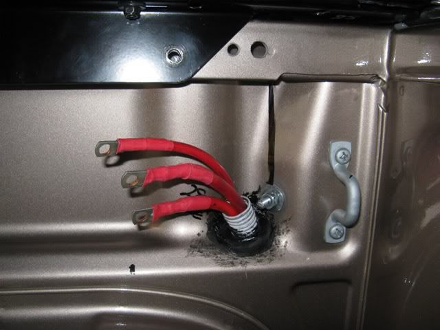
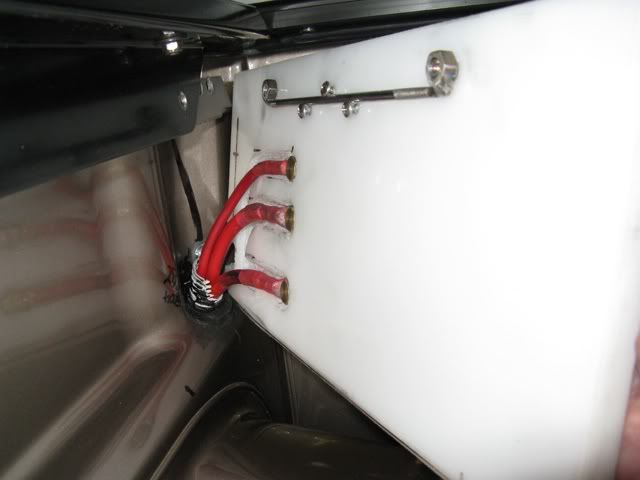
This pic shows the three leads coming through the conduit. These have been terminated using a hydraulic crimper and the open ends tipped with silver solder. They have then been covered with two pieces of heat shrink tubing.
You can see the earth bolt from where aux battery earth, earth to the board (fridge, Anderson and trailer socket) will originate.
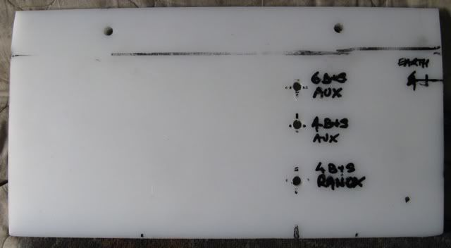
Next pic shows the plan for brass positive terminal bolts.
It also shows an earth (incorrect... have moved it) brass bolt position.
Next pix reveals how the leads were entrenched in the rear of the board - this brings them flush to the rear plane.
I now intend to adhere 1/4" rubber sheet to the tub wall to further insulate the terminals.
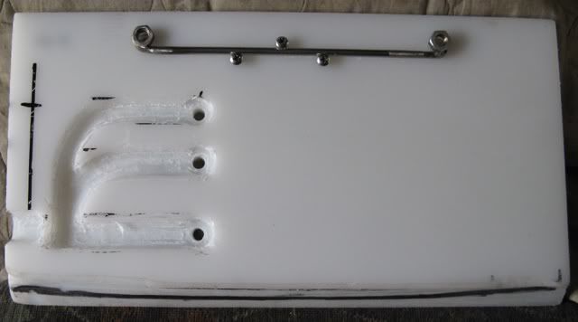
Next pic shows the bolts screwed into position holding the terminals in place prior to fitting to the underside of the canopy frame.
You can see the stainless rod and two stainless nuts Tigged into position - these are held to the back of the board by three s/steel self tappers..... to afford the stainless bolts to be screwed in blind when the board is in position...
Final pic for today is of the board bolted in place.....
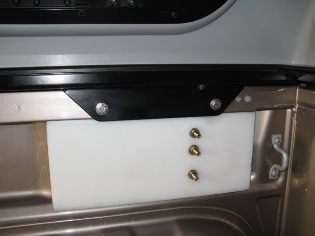
Next step it to remove it again, adhere rubber sheet to the tub wall and to make up the earth leads - hopefully this will then amount to the board being finally fitted.......
Then arrangements for RanOx, load change-over relays and fridge relay to be mapped - these will all be fitted and connections made with the board in situ.....
sorry for the novel..... might help those considering supply to the tub....
frats,
Rosco
This time we're inside the tub.
This pic shows the three leads coming through the conduit. These have been terminated using a hydraulic crimper and the open ends tipped with silver solder. They have then been covered with two pieces of heat shrink tubing.
You can see the earth bolt from where aux battery earth, earth to the board (fridge, Anderson and trailer socket) will originate.
Next pic shows the plan for brass positive terminal bolts.
It also shows an earth (incorrect... have moved it) brass bolt position.
Next pix reveals how the leads were entrenched in the rear of the board - this brings them flush to the rear plane.
I now intend to adhere 1/4" rubber sheet to the tub wall to further insulate the terminals.
Next pic shows the bolts screwed into position holding the terminals in place prior to fitting to the underside of the canopy frame.
You can see the stainless rod and two stainless nuts Tigged into position - these are held to the back of the board by three s/steel self tappers..... to afford the stainless bolts to be screwed in blind when the board is in position...
Final pic for today is of the board bolted in place.....
Next step it to remove it again, adhere rubber sheet to the tub wall and to make up the earth leads - hopefully this will then amount to the board being finally fitted.......
Then arrangements for RanOx, load change-over relays and fridge relay to be mapped - these will all be fitted and connections made with the board in situ.....
sorry for the novel..... might help those considering supply to the tub....
frats,
Rosco
- rosco01
- Posts: 303
- Joined: Sun, 02 Aug 2009 8:21 +0000
Re: Fridge/slide/power
![]() by Alby on Sat, 06 Feb 2010 3:06 +0000
by Alby on Sat, 06 Feb 2010 3:06 +0000
Nice work Rosco, very neat. I can see that you have put a lot of time into it.
Can't help but notice how clean your truck is, is this being done on the showroom floor pre delivery ???
I used those resetable breakers as well, reckon they are a good idea not having to source replacement fuses.
Can't help but notice how clean your truck is, is this being done on the showroom floor pre delivery ???
I used those resetable breakers as well, reckon they are a good idea not having to source replacement fuses.
On the internet you can be anything you want. It is strange that so many people choose to be stupid!
-

Alby - Posts: 6673
- Joined: Tue, 03 Jul 2007 1:00 +0000
- Location: Sydney, NSW
Re: Fridge/slide/power
![]() by jakelux on Sat, 06 Feb 2010 3:36 +0000
by jakelux on Sat, 06 Feb 2010 3:36 +0000
Wow.. Great job.. i wish i had the patients and time to do this.
Cant wait to see it all finished!!
Jake
Cant wait to see it all finished!!
Jake
-

jakelux - Moderator
- Posts: 2582
- Joined: Mon, 12 Oct 2009 5:38 +0000
- Location: MELBOURNE, AUSTRALIA
Re: Fridge/slide/power
![]() by rodw on Sat, 06 Feb 2010 7:33 +0000
by rodw on Sat, 06 Feb 2010 7:33 +0000
Looks great Rosco! It must give you a buz to actually be nearing the end of this project. Rather than rubber sheet, you could consider really thin cutting board. Ikea does a coloured 2mm thick one. I use a couple for camping. Trimmed one down to fit on top of a stackable plastic crate whoch works well. Yo ucan still stack crates on top of it.
-
rodw - Posts: 3195
- Joined: Tue, 19 Feb 2008 2:00 +0000
- Location: Brisbane, QLD
Re: Fridge/slide/power
![]() by rosco01 on Sun, 07 Feb 2010 6:10 +0000
by rosco01 on Sun, 07 Feb 2010 6:10 +0000
thanks folk,
Nah - this little truck won't be getting a chance to earn it's keep until we get the van.....
It has done day trips and a week away Melb - Broken Hill - Dubbo - Hay - Melb to get some k's up for its first service.... and - less than 20k's on dirt...... does this make me a 4wd person.....?
We bought it to haul the van.... it basically will be a tow vehicle.... and one day ventures into the scrub whilst away....
Rod, yes - you are correct and it would be an excellent idea to use a cover board... I have in fact used one, but had to gouge into it..... the position I have mounted this board is behind the frame of the canopy.... and it's a fairly "close" fit to get it in with fittings attached - I find that I can keep the leads in place with my fingers until it gets bolted into position - they won't come out of their grooves once it's bolted down.... the rubber sheet idea is a "just in case" position - it will be adhered to the wall of the tub behind the board.....
More today - hope to have it back in and ready to mount up the hardware.....
Yes indeed, those Jayco circuit breakers offer a few advantages over fuses... and can be used as switches to isolate when not needed.
I will fit one on the supply from the aux battery to the board.
It would now appear that RanOx is going to be mounted vertically - it sits too far below the canopy frame to be able to read the LCD screen - will have to fabricate a mount above the distribution boards..... more thinking to come.....
frats,
Rosco
- rosco01
- Posts: 303
- Joined: Sun, 02 Aug 2009 8:21 +0000
Re: Fridge/slide/power
![]() by rodw on Sun, 07 Feb 2010 7:24 +0000
by rodw on Sun, 07 Feb 2010 7:24 +0000
rosco01 wrote:
It would now appear that RanOx is going to be mounted vertically - it sits too far below the canopy frame to be able to read the LCD screen - will have to fabricate a mount above the distribution boards..... more thinking to come.....
If I add one, it will sit the same way, but I can mount it to my drawer fame. Maybe yo could bend up some stirrups out of 3mm flat ally. shaped like a flat saddle, mount the ranox to it and then screw it onto the tub.
- Code: Select all
     -------
     |     |
   --       --
I've got some 20mm x 3mm flat ally that would be perfect for this. Make 2 stirrups.
Alternatively, bolt the rannox onto some cutting board with countersunk screws, then mount the board the same wway.
-
rodw - Posts: 3195
- Joined: Tue, 19 Feb 2008 2:00 +0000
- Location: Brisbane, QLD
Re: Fridge/slide/power
![]() by rosco01 on Sun, 07 Feb 2010 11:31 +0000
by rosco01 on Sun, 07 Feb 2010 11:31 +0000
Thanks Rod,
my plan at present it to mount it to the canopy frame vertically - and make up some saddles fitted to the board so that the RanOx is in a vertical plane.
This way - when the side window is opened, the LCD readout and toggle switches are in full view below the canopy.
Have finally managed to fit the board permanently - I fitted the 70 A circuit breaker for the aux battery where I intended to terminate earth on the board.... all power sources will now run horizontally from right to left.
Aux earth is now on the uppper l/hs of the board - this makes it easier to fit earth to the fridge, Anderson plug and trailer socket - they will all pass up under the canopy frame.
Might do a bit more in a few mins.... very happy to have that board finally fitted.....
Tested voltage drops again - same as before - 0.01 volt.... between crank battery and tub terminals/earth - no load.
Ran multi-meter over all connections.... happy to report all as should be....
frats,
Rosco
- rosco01
- Posts: 303
- Joined: Sun, 02 Aug 2009 8:21 +0000
Re: Fridge/slide/power
![]() by rodw on Sun, 07 Feb 2010 4:39 +0000
by rodw on Sun, 07 Feb 2010 4:39 +0000
Geez Roso, I wish my car was as clean as yours.  Every time I came inside, I had to wash the dirt out of my face and hair that had fallen down on top of me. So hard to get the muck off even with a Gerni.
-
rodw - Posts: 3195
- Joined: Tue, 19 Feb 2008 2:00 +0000
- Location: Brisbane, QLD
Re: Fridge/slide/power
![]() by rosco01 on Mon, 08 Feb 2010 11:41 +0000
by rosco01 on Mon, 08 Feb 2010 11:41 +0000
It won't stay that way, Rod.... it's only because we are waiting for the van that it isn't getting any use.....
We get to choose the days we take it out for a run...... that luxury won't exist when we're out around the block.....
Yes, I have spent years under cars poking and prodding away at stuff - only to make the same mistake time and time again..... off to the tap to try and get grit out of my eyes......
With the onset of senility, a safeguard usually arrives in unison to protect us..... it's called "reading glasses"...... best little "concession" ever suffered.....
As for the face and hair - the hair's gone..... the face is better left "camouflaged"....... drunk gives way to sober, but ugly lasts forever......
frats,
Rosco
- rosco01
- Posts: 303
- Joined: Sun, 02 Aug 2009 8:21 +0000
Re: Fridge/slide/power
![]() by rodw on Mon, 08 Feb 2010 12:30 +0000
by rodw on Mon, 08 Feb 2010 12:30 +0000
rosco01 wrote:it's called "reading glasses"...... best little "concession" ever suffered.....
rosco, did not help me much on the weekend. I have worn glasses most of my life and relied on them quite a bit to protect my eyes and a bit of hot drill swarth bypassed the glasses and lodged right in the corner of my eye where it proceeded to sizzle. I wasn't game to move in case if fell right into my eye
One good thing though as this old age sets in, my eyesight is slowly being corrected by onset of the same thing that has you reaching for your reading glasses. Now I have to take my glasses off to read (or look under them) these days.....
-
rodw - Posts: 3195
- Joined: Tue, 19 Feb 2008 2:00 +0000
- Location: Brisbane, QLD
Re: Fridge/slide/power
![]() by rosco01 on Tue, 09 Feb 2010 9:16 +0000
by rosco01 on Tue, 09 Feb 2010 9:16 +0000
Life is a constant rate of balance, Rod..... what you miss out on in your youth - sometimes is granted when needed.....
I'm still waiting to learn that my deceased parents were in fact millionaires..... and my inheritance has just been found....
I had to cringe when I read of your swarfe branding....... I must get larger glasses.... just the thought....
I set myself on fire whilst MIG welding under my EK once..... had never welded "overhead" before and lay underneath in overalls...... I learned that a welding helmet does not afford viewing of flame.... must have looked like Mrs Doubtfire from the neighbours perspective..... got a pair of overalls which look like they've had some crazy overheated bra worn under them.......
Back to the task.... yesterday crimped 8 B&S into the terminals of the 50A Anderson Plug.... had to "trim" about eight of the very fine strands to get them in...... did not silver solder this time.... just heat shrink.
About to do the same for the trailer socket pos and earth - all these will be "driven" by relays from the distribution board.
Now looking for some relays with terminals which can accept nuts/bolts and 6 B&S cable.....
These relays will only be energised when the engine is running (load change over relay).... so there isn't concern over constant drain.
The fridge relay will have aux battery power supplied to the 87A terminal (normally closed) - this way, it will not have a current draw when the fridge is being supplied by the aux battery.....
Still working on more plans....
frats,
Rosco
- rosco01
- Posts: 303
- Joined: Sun, 02 Aug 2009 8:21 +0000
Re: Fridge/slide/power
![]() by rosco01 on Wed, 10 Feb 2010 10:49 +0000
by rosco01 on Wed, 10 Feb 2010 10:49 +0000
Ok - just a bit more...
Found some 70A relays yesterday - about $14 each - they have two large terminals which will be drilled and allow the lugs of the 6 B&S to be bolted to them - the coil terminals are small spade - and will suit the change-over relay.
I have now removed the ARB earth (joke) from the trailer socket and replaced the lead with an 8 B&S.
The trailer aux pin (or rev lights) is now fitted with another 8 B&S.
I have crimped up the Anderson plug (50A) and run 6 B&S leads to it.
These rear leads now run through 25 mm conduit - the Hilux has a great spot for running conduit across the back.
I am currently running the conduit up through the l/hs tail-light and it will pass along under the tub upper l/hs top.
This will afford all the rear wiring to be connected up at the distribution board.
Anyone who has the ARB rear step bar...... there is precious little room to pass leads between the chequer-plate and the body - I have attempted to temporarily remove the chequer-plate - but it is adhered to the bar frame......
I will fit rubber tubing over the leads and hold them in situ with Sikaflex. They will be cable tied on both sides...
frats,
Rosco.
- rosco01
- Posts: 303
- Joined: Sun, 02 Aug 2009 8:21 +0000
Re: Fridge/slide/power
![]() by rosco01 on Wed, 10 Feb 2010 5:27 +0000
by rosco01 on Wed, 10 Feb 2010 5:27 +0000
Just before the thunderstorm hits....
Removed the rear l/hs tail-light assembly and finally managed to remove the connector.
There is a cavity (possibly pre-considered by Toyota) for running 25 mm conduit up the outer side of the tail-light assembly - it is a perfect fit.
The only down side is that underneath the top edge of the body/tub is - at the rear corner - the conduit will not pass through the gap..... I had to drill a series of small holes and then grind out with a small rotary tool..... it doesn't need much and does not need to cut into the double skin.. this pic shows the upper left hand side corner of the tub - behind the upper tail-light cavity...
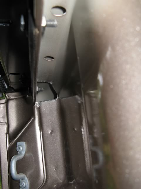
With the tail-light removed, this pic reveals just how well this sized conduit will fit into the tail-light cavity.
I removed the original stand-off wiring conduit holder and fitted a rubber grommet - this now holds the 25 mm conduit and that of the l/hs wiring loom... this large grommet was made from a blind plug with the centre cut out to form the grommet hole - it's at the end of the conduit..... they are available from Clark rubber for around the $4 mark.... can't remember the size - but guessing, around 2 1/2".....
The hole for this is already in the body underside...
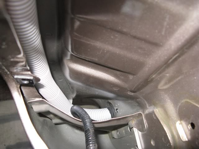
With the power conduit in place - this pic shows just how well the design of the body has been made ... presumably for this purpose....
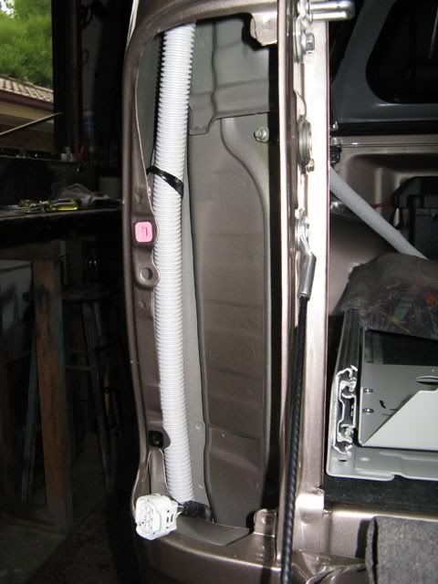
From inside the tub, this pic shows how the conduit will run neatly above the bots/nuts holding the canopy to the tub..

Finally for today - this is now what I have in waiting for connecting up to the distribution board.....
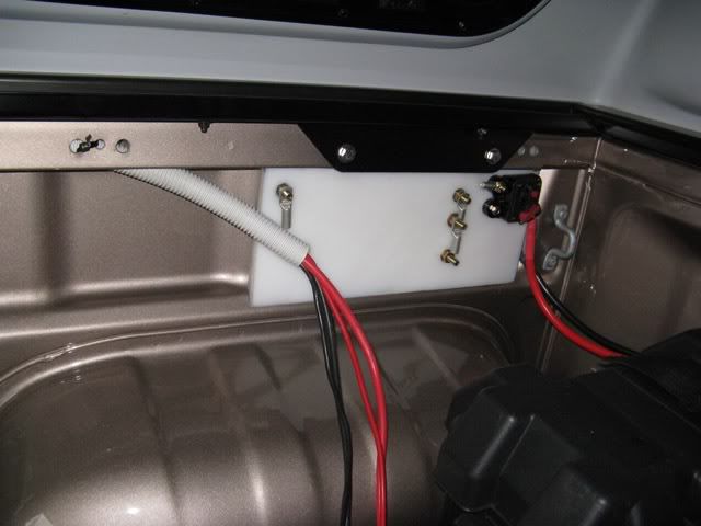
In the above pic, you can also see the 70A resettable circuit breaker for battery supply.
I have moved the common earth to the l/hs of the board for this purpose. Fridge, Anderson plug and trailer socket earth will all be connected to this terminal.
You can also see the two 6 B&S leads for the Anderson plug, and the two 8 B&S leads for the trailer socket earth and aux power - all four leads fit very nicely into this 25 mm conduit - 20 mm inside diameter..
frats,
Rosco
Removed the rear l/hs tail-light assembly and finally managed to remove the connector.
There is a cavity (possibly pre-considered by Toyota) for running 25 mm conduit up the outer side of the tail-light assembly - it is a perfect fit.
The only down side is that underneath the top edge of the body/tub is - at the rear corner - the conduit will not pass through the gap..... I had to drill a series of small holes and then grind out with a small rotary tool..... it doesn't need much and does not need to cut into the double skin.. this pic shows the upper left hand side corner of the tub - behind the upper tail-light cavity...
With the tail-light removed, this pic reveals just how well this sized conduit will fit into the tail-light cavity.
I removed the original stand-off wiring conduit holder and fitted a rubber grommet - this now holds the 25 mm conduit and that of the l/hs wiring loom... this large grommet was made from a blind plug with the centre cut out to form the grommet hole - it's at the end of the conduit..... they are available from Clark rubber for around the $4 mark.... can't remember the size - but guessing, around 2 1/2".....
The hole for this is already in the body underside...
With the power conduit in place - this pic shows just how well the design of the body has been made ... presumably for this purpose....
From inside the tub, this pic shows how the conduit will run neatly above the bots/nuts holding the canopy to the tub..
Finally for today - this is now what I have in waiting for connecting up to the distribution board.....
In the above pic, you can also see the 70A resettable circuit breaker for battery supply.
I have moved the common earth to the l/hs of the board for this purpose. Fridge, Anderson plug and trailer socket earth will all be connected to this terminal.
You can also see the two 6 B&S leads for the Anderson plug, and the two 8 B&S leads for the trailer socket earth and aux power - all four leads fit very nicely into this 25 mm conduit - 20 mm inside diameter..
frats,
Rosco
- rosco01
- Posts: 303
- Joined: Sun, 02 Aug 2009 8:21 +0000
-
rodw - Posts: 3195
- Joined: Tue, 19 Feb 2008 2:00 +0000
- Location: Brisbane, QLD
Re: Fridge/slide/power
![]() by rosco01 on Sat, 13 Feb 2010 6:47 +0000
by rosco01 on Sat, 13 Feb 2010 6:47 +0000
Ok Just a little bit more....
One problem fixed, another looming....
With the ARB rear step bar, I had to grind away a section of the chequer-plate for the heavy cabling to the Anderson Plug. It just wasn't possible to run these leads (with protective covers) between the plate and the front frame of the bar..
I then found out that the aluminium chequer plate cannot be removed from the rear bar without threatening to damage it.... so, armed with a small rotary tool, ground and ground..... and ground away until I created an opening.....
A few slips and "oaths" and a lot of not wanting to go any further with it - eventually gave way to cutting two 40 mm slots from the leading edge to the rear of the front bar. I removed a rectangular section of about 30 mm deep and angled up the remaining 10 mm to give some deflection, should something project into the opening.
The 6 B&S (both pos and neg) was fed through some 9.5mm ID trans hose and passed over the front bar of the assembly.
Connections were made to the Anderson and it was mounted to the rear face of the front bar (protected).
The resulting gap with a large red and black power lead showing through was offensive....
I then decided to fabricate a small aluminium "box" (40 mm x 40 mm with an angled leading edge) and fitted it into the gap - the sides are bent at right angles allowing it to be adhered with Sikaflex to the underside of the chequerplate.... I still think it looks ugly, - I'd been ranting about it for a couple of days to my wife..... on "unguided" inspection - looing closely for a "hole" wanted to know what I'd been on about...... I pointed to the "box" and was told told that it looked "factory"...... show pix when I upload them.... looks crap.... will have to come up with something better....
Now the fix bit....
I have managed to fit brackets inside the upper recess under the tub "lip" to support the conduit.
These are held in place with a small self tapper with a washer. These brackets are available from Bunnings - but they need to be straightened and cut down quite a bit... they are the single hole bracket which comes with a nail fitted.... for 25 mm conduit..
I fitted two right hand conduit "elbows" to create the change in direction of the conduit from the recess to the distribution board. It is now in situ whilst the cement dries. I will secure it to the board with a saddle clamp.
I now have all wiring in place for connection to the relays and RanOx.... this is all that now remains of this project.....
Post up some pix soon - very happy to be almost finished on this little venture...
frats,
Rosco
- rosco01
- Posts: 303
- Joined: Sun, 02 Aug 2009 8:21 +0000
49 posts
• Page 2 of 3 • 1, 2, 3
Who is online
Users browsing this forum: No registered users and 47 guests
![]()