I have got my high idle working - further more it's even adjustable
I used 2 pots, one 50k and the other 10k to wire things up, the 10k to step the voltage from the 50k pot down the 0.8v on the reference line.
Testing indicates my 50k and 10k are FAR too big but as I only plan on using them to set the idle speed to what I want and then to measure their resistance to replace them with static resistors it's not a big issue.
Further I can use any switch I want as the idea is to have the resistors on a line that's connected through a relay.
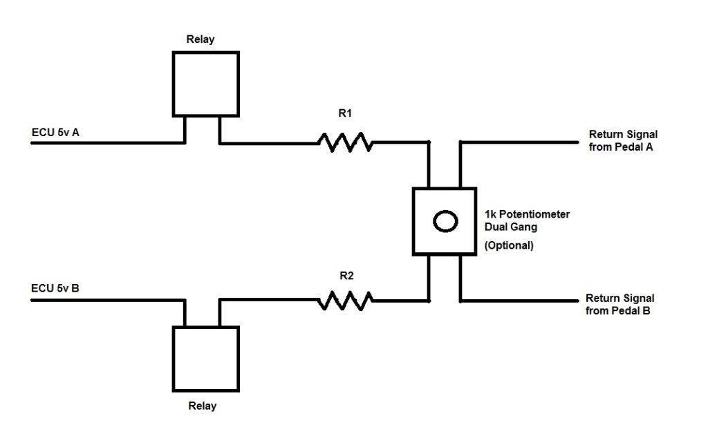
I'm uploading my test video now to youtube to update later. I'll also post a schematic of my circuit including all details should anyone else want to copy, however I'll stress right now this is something I developed for myself and I can't promise it will work on a universal level as I know the ECU's are different from mid 06 onwards (mines an 05, a pretty simply ECU in comparison)
However should anyone wish to copy mine (as I'll be making mine non-adjustable) I'll try and work out resistor values through testing so people can customise their own versions to suit whatever idle speed they want. I'll also try some 1k POTs to see if I can make it adjustable but be aware that if one POT is set too low you will possibly get it running full throttle hence my preference to have it set at a certain level instead of adjustable.
The other good news is that the components (not including the switch, as that varies depending which one you go for) can probably be had for less than $10 or so.
Video should be up shortly