Idle up?
Re: Idle up?
![]() by StevenS on Thu, 31 May 2012 9:11 +0000
by StevenS on Thu, 31 May 2012 9:11 +0000
-

StevenS - Posts: 1172
- Joined: Tue, 21 Feb 2012 7:49 +0000
- Location: SE QLD
Re: Idle up?
![]() by andy666 on Thu, 31 May 2012 9:13 +0000
by andy666 on Thu, 31 May 2012 9:13 +0000
The out puts for each side off the pedal at full throttle are about 3.2V and 4.2V so will have to be compensated for or could throw a code.
I wasn't going to post anything this early, but if I can get this sorted in to a working system I might build some kits. If I can't then I might fry my ECM
-

andy666 - Posts: 908
- Joined: Sun, 12 Dec 2010 6:07 +0000
- Location: Brisbane
Re: Idle up?
![]() by kyle300exc on Thu, 31 May 2012 9:20 +0000
by kyle300exc on Thu, 31 May 2012 9:20 +0000
Never, under any circumstances, take a sleeping pill and a laxative on the same night.
-

kyle300exc - Moderator
- Posts: 8567
- Joined: Mon, 20 Sep 2010 12:32 +0000
- Location: Narellan
Re: Idle up?
![]() by Noidea on Thu, 31 May 2012 9:21 +0000
by Noidea on Thu, 31 May 2012 9:21 +0000
My Build Thread: viewtopic.php?f=41&t=8528&start=40
My Shed: http://www.newhilux.net/myshed.php?view=1&id=1538
-

Noidea - Posts: 1098
- Joined: Thu, 18 Feb 2010 7:17 +0000
- Location: Hornsby Area, NSW
Re: Idle up?
![]() by redirtlux on Sun, 10 Jun 2012 12:11 +0000
by redirtlux on Sun, 10 Jun 2012 12:11 +0000
The pajero and all the old cars had very advanced engineering
Wish I had it in my d4d hilux to track down the engine noise.
- redirtlux
- Posts: 9
- Joined: Sat, 31 Mar 2012 5:24 +0000
Re: Idle up?
![]() by StevenS on Sun, 17 Jun 2012 3:35 +0000
by StevenS on Sun, 17 Jun 2012 3:35 +0000
The bad news is that the accelerator pedal position sensor is not a variable resistor - it's actually a sort of magnetic switch
out of the 6 wires that go in, it's actually 2 pairs of 3 - just as the factory wiring diagram suggests. I joined 6 wires into the sensor harness so I could experiment with the sensor plugged in and the engine running.
By directly shorting some wires I was able to get the engine to rev. I was working on only 1 of the pair of 3 wires. Despite only 1 of the pair being shorted, the engine revved quite a bit before the ECU noticed a problem and dropped the revs back down. I could do this 2 or 3 times before it engaged limp mode. This seems to suggest there is actually a bit of leeway in the sensor readings before the ECU detects a problem.
The "kinda" good news is that the sensor terminals themselves have a resistance value that is static. I should be able to make a basic PCB that would reflect those same resistance values which when connected would be treated like a pedal at the rest position. I would then need to change the resistance values slightly to hopefully get it working.
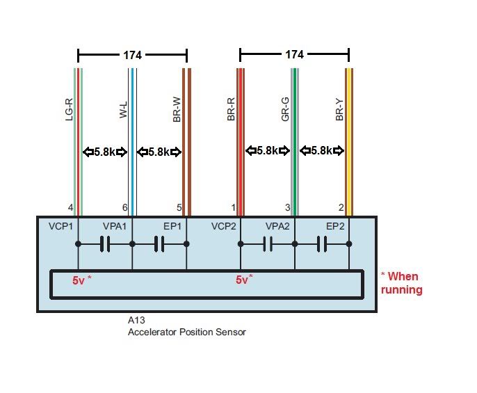
In case anyone else wants to have a play I've provided the values I found on the sensor below with the ECU loom unplugged. With the loom plugged in and the engine running there was 5v present at the wires indicated.
-
StevenS - Posts: 1172
- Joined: Tue, 21 Feb 2012 7:49 +0000
- Location: SE QLD
Re: Idle up?
![]() by lmichie on Sun, 17 Jun 2012 4:34 +0000
by lmichie on Sun, 17 Jun 2012 4:34 +0000
Lachlan
-

lmichie - Posts: 457
- Joined: Sun, 15 Nov 2009 7:52 +0000
- Location: Baulkham Hills, NSW
Re: Idle up?
![]() by StevenS on Sun, 17 Jun 2012 5:06 +0000
by StevenS on Sun, 17 Jun 2012 5:06 +0000
The problem you might have with the second sensor is just how little it actually moves. From rest to full throttle the internal adjuster in the sensor would be lucky to turn 90 degrees
I had a fair bit on this afternoon so I could experiment as much as I would have liked to. I've also sent an email to sprint booster to ask for advice as something like this would be a piece of piss for them
-
StevenS - Posts: 1172
- Joined: Tue, 21 Feb 2012 7:49 +0000
- Location: SE QLD
Re: Idle up?
![]() by lmichie on Sun, 17 Jun 2012 5:18 +0000
by lmichie on Sun, 17 Jun 2012 5:18 +0000
-
lmichie - Posts: 457
- Joined: Sun, 15 Nov 2009 7:52 +0000
- Location: Baulkham Hills, NSW
Re: Idle up?
![]() by StevenS on Sun, 24 Jun 2012 12:09 +0000
by StevenS on Sun, 24 Jun 2012 12:09 +0000
The throttle assembly is a dual output hall effect sensor, with the difference in input signals used to check faults.
Of the above picture, the abbreviations are for the following
VCP1 - main feed from ECU
VPA1 - main input signal to ECU
EP1 - Earth reference
Below is what I've found from researching Toyota electronic throttles.
The secondary lot are for error checking, and aren't used directly for throttle response - however if there is a difference too large between VPA1 and VPA2 then the ECU will log a fault code and eventually result in limp mode.
VPA1 and VPA2 should never read the same (at least not within 0.02v), but rather a gap should remain in the output that is constant. This gap needs to be measured, and is usually in the vicinity of 0.5v
A dual gang POT connecting VCP1 / VPA1 and VCP2 / VPA2 (with an additional resistor in line between VCP1/VPA1) should work as an electronic throttle.
Work on my new tray is taking priority at the moment and I do hope to test the above soon but if this information can be of help to anyone please use it
-
StevenS - Posts: 1172
- Joined: Tue, 21 Feb 2012 7:49 +0000
- Location: SE QLD
Re: Idle up?
![]() by lmichie on Sun, 24 Jun 2012 12:31 +0000
by lmichie on Sun, 24 Jun 2012 12:31 +0000
-
lmichie - Posts: 457
- Joined: Sun, 15 Nov 2009 7:52 +0000
- Location: Baulkham Hills, NSW
Re: Idle up?
![]() by StevenS on Sun, 24 Jun 2012 12:57 +0000
by StevenS on Sun, 24 Jun 2012 12:57 +0000
Wiring in parallel would be the best option as it would allow the foot pedal to be used with the idle speed already increased.
A POT that has around a 5v drop would probably let you set the idle speed all the way to mimicking WOT. The voltage wouldn't "add" to that coming from the foot pedal, it would simply be that the foot pedal would have no effect (or very little) up to the point where it would be supplying a higher voltage to the ECU than the POT does.
It would still be wise to connect the POT via a switchable relay as POTs have on occasion been known to fail and go open circuit - last thing you would want is have full throttle when not expecting it.
-
StevenS - Posts: 1172
- Joined: Tue, 21 Feb 2012 7:49 +0000
- Location: SE QLD
Re: Idle up?
![]() by StevenS on Sun, 24 Jun 2012 1:21 +0000
by StevenS on Sun, 24 Jun 2012 1:21 +0000
1.6 to 4v
0.8 to 3.2v
So a 0.8v difference is what needs to be maintained to prevent error codes popping up.
I only had a quick test so I couldn't check which line was VPA1 or VPA2, however it makes little difference as long as that difference is kept.
-
StevenS - Posts: 1172
- Joined: Tue, 21 Feb 2012 7:49 +0000
- Location: SE QLD
Re: Idle up?
![]() by olcoolone on Sun, 24 Jun 2012 2:22 +0000
by olcoolone on Sun, 24 Jun 2012 2:22 +0000
In other words it acts a a sort of fall back system so the ECM will not increase engine speed by accident of component failure.
I would say there would be two different output voltages for VCP1 and VCP2 and both would move in a linear scale.
A good thing to do would be to data log both outputs at the same time and variable pedal positions.
It might pay to put your resources into finding out how the ECU works then back tracing.
Have a look at this that I just found....
http://www.thetruthaboutcars.com/2010/0 ... explained/
http://www.safetyresearch.net/Library/P ... 022110.pdf
http://www.ncttora.com/fsm/04-06-info.t ... ip2121.pdf
Sorry guys I don't have Hilux D4D any more for on vehicle testing.
http://www.google.com.au/search?sugexp= ... 0&bih=1032
Might be of use
-
.JPG)
olcoolone - Posts: 675
- Joined: Sun, 07 Jan 2007 12:00 +0000
- Location: Modbury, SA
Re: Idle up?
![]() by StevenS on Sun, 24 Jun 2012 2:41 +0000
by StevenS on Sun, 24 Jun 2012 2:41 +0000
-
StevenS - Posts: 1172
- Joined: Tue, 21 Feb 2012 7:49 +0000
- Location: SE QLD
Re: Idle up?
![]() by olcoolone on Sun, 24 Jun 2012 4:56 +0000
by olcoolone on Sun, 24 Jun 2012 4:56 +0000
-
olcoolone - Posts: 675
- Joined: Sun, 07 Jan 2007 12:00 +0000
- Location: Modbury, SA
Re: Idle up?
![]() by lais817 on Sun, 24 Jun 2012 8:32 +0000
by lais817 on Sun, 24 Jun 2012 8:32 +0000
-

lais817 - Posts: 739
- Joined: Thu, 07 Oct 2010 10:39 +0000
- Location: Geelong VIC

Re: Idle up?
![]() by andy666 on Mon, 25 Jun 2012 11:27 +0000
by andy666 on Mon, 25 Jun 2012 11:27 +0000
Finally tried out my idea for an electronic idle control today and no joy.
I made up a prototype circuit board with a dual gang potentiometer and resistors (to drop the voltage of the 1st gang the same as the standard throttle pedal) and wired it in parallel with the throttle pedal. Unfortunately as soon as I turned the ignition on the engine warning light was staying on and when I stated it there was no change in idle when I varied the potentiometer.
Maybe a non contact induction potentiometer, the same as the throttle pedal would work? But where to get one and price is the issue.
Oh well, at least everything returned to normal when I unplugged my idle control and there doesn't seem to be any damage.
-
andy666 - Posts: 908
- Joined: Sun, 12 Dec 2010 6:07 +0000
- Location: Brisbane
Re: Idle up?
![]() by olcoolone on Mon, 25 Jun 2012 1:36 +0000
by olcoolone on Mon, 25 Jun 2012 1:36 +0000
Much like a transducer works.
You will also need to do this to both isolated circuits (the primary and fail-safe).
-
olcoolone - Posts: 675
- Joined: Sun, 07 Jan 2007 12:00 +0000
- Location: Modbury, SA
Who is online
Users browsing this forum: No registered users and 25 guests
![]()