Hey mate cheers for that. Don't go to too much trouble but if you could cover what order I'm best to tackle things/what order of the instructions tripped you up it'd be great!
I already have the front indicators and parkers in my stock bull bar so shouldn't need any wiring I assume, thank god.
I'll check out the electronic instructions, sounds much better!
I'll have a mate helping but not sure how to lift the thing yet, have considered hiring an engine crane if I need to. It'll have the winch in it too... So some wiring there - D'oh! I don't have half my tools here either, no trolley jack, jack stands.... All in Melbourne.
Thanks!
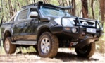
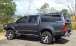
Fred's build - Monster Ride Installed - CV's replaced
Re: Fred's build.
![]() by Packdaddy on Tue, 11 Sep 2012 8:34 +0000
by Packdaddy on Tue, 11 Sep 2012 8:34 +0000
Packer
Build Thread : viewtopic.php?f=41&t=14867
'Rules are for the obedience of fools and the guidance of wise men' - Sir Douglas Bader
Build Thread : viewtopic.php?f=41&t=14867
'Rules are for the obedience of fools and the guidance of wise men' - Sir Douglas Bader
-
Packdaddy - Posts: 382
- Joined: Wed, 15 Jun 2011 10:06 +0000
- Location: Nowra, NSW
Re: Fred's build.
![]() by fredbear on Wed, 12 Sep 2012 7:35 +0000
by fredbear on Wed, 12 Sep 2012 7:35 +0000
Packdaddy wrote:Hey mate cheers for that. Don't go to too much trouble but if you could cover what order I'm best to tackle things/what order of the instructions tripped you up it'd be great!
I already have the front indicators and parkers in my stock bull bar so shouldn't need any wiring I assume, thank god.
I'll check out the electronic instructions, sounds much better!
I'll have a mate helping but not sure how to lift the thing yet, have considered hiring an engine crane if I need to. It'll have the winch in it too... So some wiring there - D'oh! I don't have half my tools here either, no trolley jack, jack stands.... All in Melbourne.
Thanks!
OK I'll step through the electronic version of the manual and point out stuff (numbers refer to ARB step number)
before starting I suggest you sort the fasteners into groups, see my pics.
1. don't forget the small screws in the grill 2 off,
2. Suggest you completely take headlights off, put them back in later,
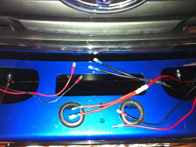
4. "relay" loom is the big one, and you have 2 x smaller "indicator" looms. ARB 's decription of colours is confusing.
5. yep green wire to red.
6. yellow goes to green and black to black. the colours are nothing to do with wire stripes!
7. see 6 above
12. at this point I plugged in the indicators to test all OK, before cable tying. see my build pics for relay locations I used (just in front of battery)
13. I also installed my HID headlight kit before cable tying.
14. I drilled welds - easy. There are 2 other brackets, I ended up removing them later on, but they are never mentioned in ARB instructions.
15. I didn't paint them.....didn't see the need.
16. I still had bar on ground on its cardboard box as a protector & started assembly of bar. Be careful not to over tighten.
17. yep double check which cage nuts go where I stuffed 4 by doing it wrong.
18. indicators attach from "inside" the bar by throwing away orig screws & replacing with ARB supplied ones, actually don't fit that well in my view
SR5 fog lights "POP" out of their housing which you need to do. Wiring extension leads are supplied. I bent the "tabs" several times in trial fitting. Still a crap mounting system. I need to use silicon or something to secure them I think. Don't finally fit Fogs just yet as you will need the access holes!
19. Dont forget to tighten wing trims before you put under plates on!!
20. I dont have winch yet - so passed on these steps.
36 I didn't get a roller fairlead....ummm does this come with winch? not sure but I have ordered one anyhow so might have a spare.
42. I lifted mine on my own. I used 2 x ratcheting straps over the gables in the shed. I used oil drums as safety items just in case a strap broke. I parked the hilux in the right spot (exactly!)
I roughly set it side to side & nipped up 2 bolts from front. I then moved it forward back & nipped up bolts on impact bar. I was to close on bumper over rides so had to move bar away a bit. I readjusted side - side, I used a visual sight line along side of bar to flares. Nipped up side to side again, then tweaked front to back. Thought I had it until I put a ruler on gaps to flares on each side. I had ~15mm and 22mm.....somehow a bit twisted. Push pull & got it there. tightened everything up.
43. You need a small drill to do this, my AEG drill was to long that made it hard to get in for top ones.
44. dont forget this step!!! (i did!)
47. I fitted grill to plate before fixing grill to vehicle, couldn't get it to connect otherwise.
50 the lips go up! to hold the mudguard plastic (as far as I know!)
51 not yet - need to cut plastic first!
52 dont cable tie yet!
53. stanley knife works OK. to cut plastic.
Took me 4pm-11pm sat night then 8am - 9pm sunday to do bar + exhaust (~3 hrs) + mount spots , all done on my own.
Hope that helps some. Happy to help if you need more. pm me if you want a mobile number so you can txt me if you want.
- fredbear
- Posts: 150
- Joined: Wed, 19 Nov 2008 9:56 +0000
- Location: SA
Re: Fred's build.
![]() by Packdaddy on Thu, 13 Sep 2012 10:24 +0000
by Packdaddy on Thu, 13 Sep 2012 10:24 +0000
Mate, thanks for that, awesome bit of info!
I won't be able to get stuck into it till next weekend I think. Might have a play with the bits in the mean time, try getting it started at least.
It's funny how it seems like such a simple job but realistically there's a lot more to it... Yet no one's put together a thread on it.... Crap, guess I just dobbed myself in haha. See how that goes! Hopefully not having the do the wiring will simplify it a tad.
My winch has rope on it and so came with a fairlead although it looks like I might need an offset one. Pretty sure tigerz offered to swap it over if I needed
Thanks again mate I'll get in touch if need be
Mark
Packer
Build Thread : viewtopic.php?f=41&t=14867
'Rules are for the obedience of fools and the guidance of wise men' - Sir Douglas Bader
Build Thread : viewtopic.php?f=41&t=14867
'Rules are for the obedience of fools and the guidance of wise men' - Sir Douglas Bader
-
Packdaddy - Posts: 382
- Joined: Wed, 15 Jun 2011 10:06 +0000
- Location: Nowra, NSW
Re: Fred's build.
![]() by fredbear on Thu, 13 Sep 2012 6:48 +0000
by fredbear on Thu, 13 Sep 2012 6:48 +0000
Packdaddy wrote:Mate, thanks for that, awesome bit of info!
I won't be able to get stuck into it till next weekend I think. Might have a play with the bits in the mean time, try getting it started at least.
It's funny how it seems like such a simple job but realistically there's a lot more to it... Yet no one's put together a thread on it.... Crap, guess I just dobbed myself in haha. See how that goes! Hopefully not having the do the wiring will simplify it a tad.
My winch has rope on it and so came with a fairlead although it looks like I might need an offset one. Pretty sure tigerz offered to swap it over if I needed
Thanks again mate I'll get in touch if need be
Mark
No Probs
If / when I get time I was going to write it up also. Have lots of pics I took along the way.
I also ordered the TigerZ winch with rope. But I also ordered a roller fairlead at the time. Still waiting on delivery of the winch. I will find out if winch in stall can be done after wards
If you get stuck in your "mental rehearsal" or when doing it just holler.
- fredbear
- Posts: 150
- Joined: Wed, 19 Nov 2008 9:56 +0000
- Location: SA
Re: Fred's build.
![]() by fredbear on Sun, 16 Sep 2012 7:16 +0000
by fredbear on Sun, 16 Sep 2012 7:16 +0000
Wiring HID Spots
I searched the net & could not find anything that is the same as the following so now I have it working I thought I'd post my wiring method up.
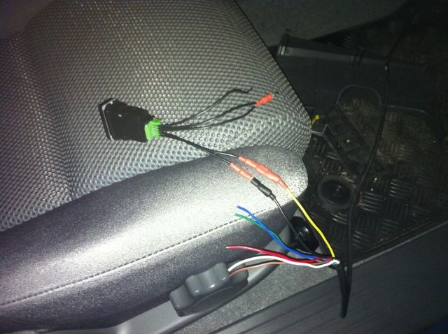
Because I want to be able to switch several things eg the Spots, a worklight in the rear, a compressor etc etc, I didn't want to run multiple single wires through the firewall. It looks messy under the dash, and 1/2 doz red wires can be hard to trace, so I had another idea. I simply ran a length of 7-core trailer wire from the switch area on right of steering column through the firewall to near the battery. With one wire an earth I can now use the other 6 colours as "switch" wires for the other items I want to be able to turn on/off.
I went to repco & got a 10m roll of 7 Core (~$35) + some connectors + shrink tube
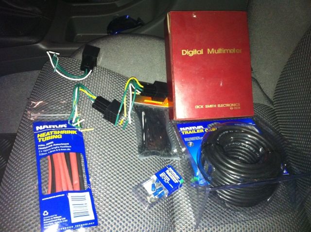
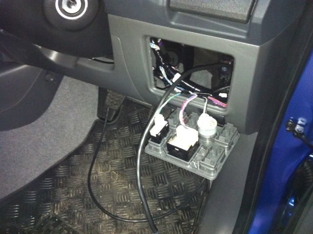
Second step was to make a hole through the firewall & find it inside.
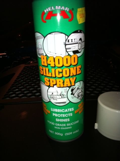
I used some of this (from $2 shop) to make it easier to feed the cable through (worked well)
And fed the cable from outside to inside, enough to reach across to driver side switch area.
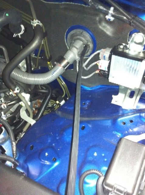
I just reached up under the panel & gently pushed it out the switch panel.
I decided to use the Black as earth and the Yellow for my spots (& blue for the aircomp)
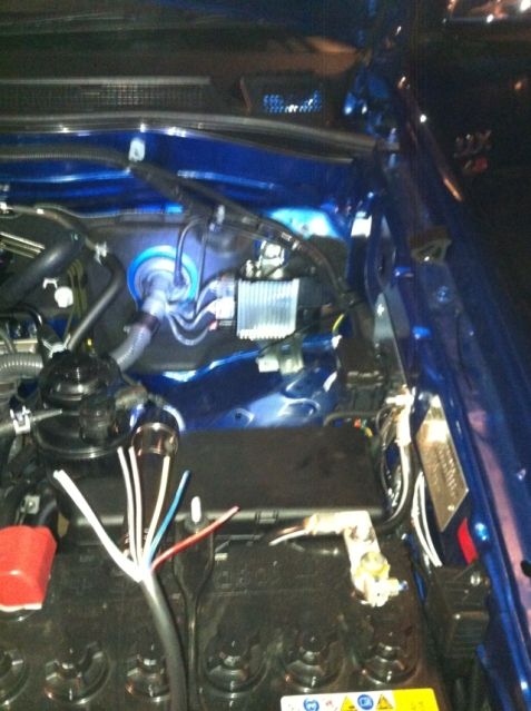
With the cable run done, I now joined the two spots together by making a "Y" junction cable. The black goes to the earth connector (or battery negative). The Red goes to pin "87".
My understanding (I'm not an auto electrician) of Relays & switches is basically this, you use a manual switch to operate an "electric switch" (a relay) which actually does the connection of power to the device.
So I need 4 wires. one from the battery, one to the spots (positive), one to the existing highbeam, and one to earth via my manual switch (yellow then black in my case).
Previously I fitted a HID headlight kit, so I got out the junction of the original headlight connector & the HID connector.
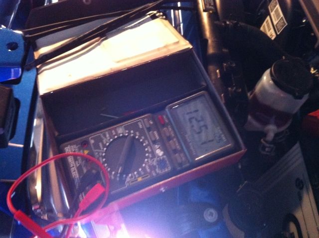
So using my multimeter I figured out the highbeam wire and the earth wire (the third wire on the connector is low beam). I am using this highbeam wire as a tigger, ie the relay will only be "live" when the highbeam is turned on.
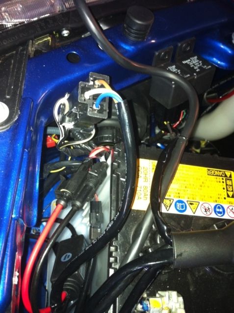
So I connected a length of red wire to the highbeam wire.
This wire will go to pin "86", and will be part of "activating" the relay and hence the spots.
Next I checked and when (and only when) highbeam was on I had 12v between my red wire and the negative battery post, so far so good.
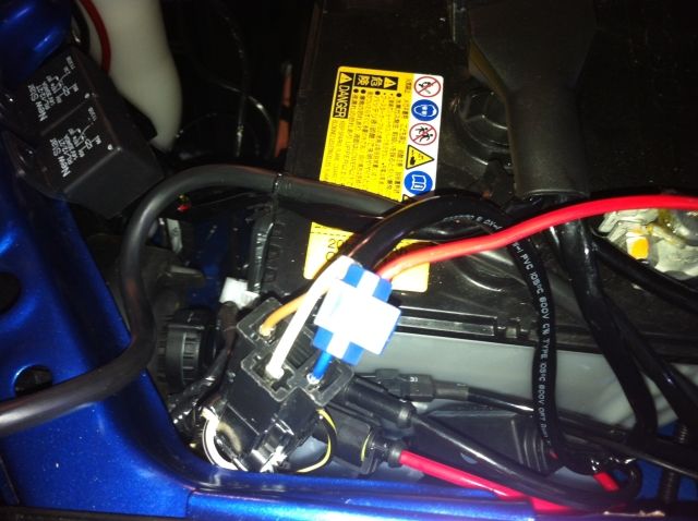
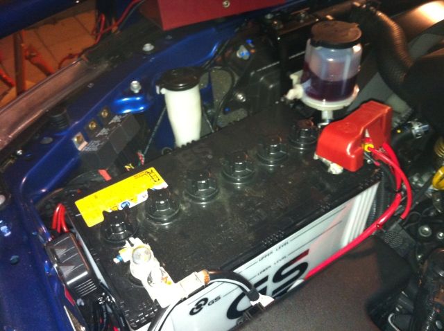
I then made up another short length of red wire with an inline fuse (15A) which goes from the Battery positive to the "30" terminal of the relay. So it will be pin 30 and pin 87 that will connect when relay is activated.
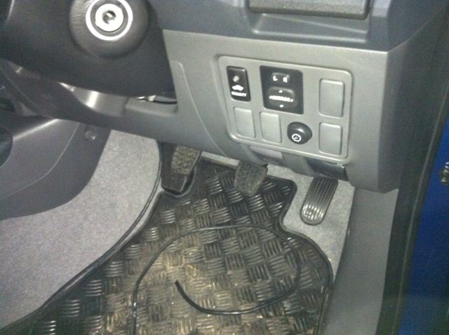
My "Yellow" wire that goes through the firewall will connect to pin "85" on the relay. Normally pin "85" would be earthed and could be, but that would mean the spots would be on every time the high beam is. Since I want highbeam both with and without spots, I am earthing it but via a manual switch ie my yellow wire goes to a switch on dash, then the black wire returns back to the battery negative. The other wires on the switch are to illuminate the switch, when active and also at night.
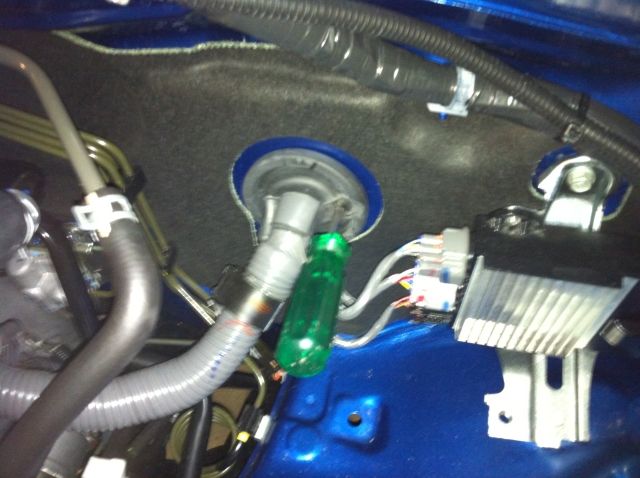
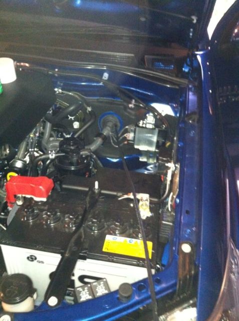
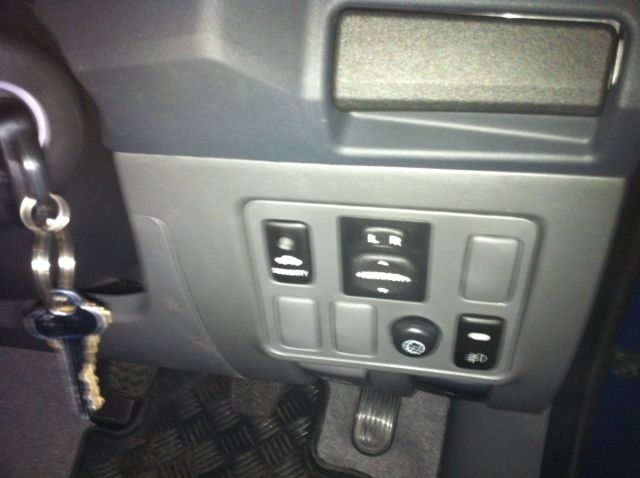
So I now have a new switch on the dash panel
A new relay mounted next to the 2 used for the ARB bullbar indicators.
And of course some extra lumens.
And best of all I'm all set with 5 more "switch wires" for other stuff (worklight, compressor & ? & ? & ? ) thanks to the 7 core through the firewall.
I searched the net & could not find anything that is the same as the following so now I have it working I thought I'd post my wiring method up.
Because I want to be able to switch several things eg the Spots, a worklight in the rear, a compressor etc etc, I didn't want to run multiple single wires through the firewall. It looks messy under the dash, and 1/2 doz red wires can be hard to trace, so I had another idea. I simply ran a length of 7-core trailer wire from the switch area on right of steering column through the firewall to near the battery. With one wire an earth I can now use the other 6 colours as "switch" wires for the other items I want to be able to turn on/off.
I went to repco & got a 10m roll of 7 Core (~$35) + some connectors + shrink tube
Second step was to make a hole through the firewall & find it inside.
I used some of this (from $2 shop) to make it easier to feed the cable through (worked well)
And fed the cable from outside to inside, enough to reach across to driver side switch area.
I just reached up under the panel & gently pushed it out the switch panel.
I decided to use the Black as earth and the Yellow for my spots (& blue for the aircomp)
With the cable run done, I now joined the two spots together by making a "Y" junction cable. The black goes to the earth connector (or battery negative). The Red goes to pin "87".
My understanding (I'm not an auto electrician) of Relays & switches is basically this, you use a manual switch to operate an "electric switch" (a relay) which actually does the connection of power to the device.
So I need 4 wires. one from the battery, one to the spots (positive), one to the existing highbeam, and one to earth via my manual switch (yellow then black in my case).
Previously I fitted a HID headlight kit, so I got out the junction of the original headlight connector & the HID connector.
So using my multimeter I figured out the highbeam wire and the earth wire (the third wire on the connector is low beam). I am using this highbeam wire as a tigger, ie the relay will only be "live" when the highbeam is turned on.
So I connected a length of red wire to the highbeam wire.
This wire will go to pin "86", and will be part of "activating" the relay and hence the spots.
Next I checked and when (and only when) highbeam was on I had 12v between my red wire and the negative battery post, so far so good.
I then made up another short length of red wire with an inline fuse (15A) which goes from the Battery positive to the "30" terminal of the relay. So it will be pin 30 and pin 87 that will connect when relay is activated.
My "Yellow" wire that goes through the firewall will connect to pin "85" on the relay. Normally pin "85" would be earthed and could be, but that would mean the spots would be on every time the high beam is. Since I want highbeam both with and without spots, I am earthing it but via a manual switch ie my yellow wire goes to a switch on dash, then the black wire returns back to the battery negative. The other wires on the switch are to illuminate the switch, when active and also at night.
So I now have a new switch on the dash panel
A new relay mounted next to the 2 used for the ARB bullbar indicators.
And of course some extra lumens.
And best of all I'm all set with 5 more "switch wires" for other stuff (worklight, compressor & ? & ? & ? ) thanks to the 7 core through the firewall.
Last edited by fredbear on Sun, 16 Sep 2012 7:54 +0000, edited 1 time in total.
- fredbear
- Posts: 150
- Joined: Wed, 19 Nov 2008 9:56 +0000
- Location: SA
Re: Fred's build.
![]() by 10 luxxxx on Sun, 16 Sep 2012 7:26 +0000
by 10 luxxxx on Sun, 16 Sep 2012 7:26 +0000
That's good idea mate with the seven core wish I had thought of that under my switch panel looks like a nest
VIEW MY BUILD viewtopic.php?f=41&t=14606
-

10 luxxxx - Posts: 1507
- Joined: Mon, 19 Dec 2011 12:37 +0000
- Location: Perth
Re: Fred's build.
![]() by LJ1930 on Sun, 16 Sep 2012 11:01 +0000
by LJ1930 on Sun, 16 Sep 2012 11:01 +0000
haha did that today and thought i was alone with the trailer wire until i saw ya post. common feed for relays under bonnet then coloured (switched wires to the in cab switch then to neg/earth to power relay coils..)
- LJ1930
- Posts: 15
- Joined: Fri, 03 Feb 2012 1:18 +0000
Re: Fred's build.
![]() by LJ1930 on Sun, 16 Sep 2012 11:03 +0000
by LJ1930 on Sun, 16 Sep 2012 11:03 +0000
fog lights not going on ya bar? sr or sr5 ?
- LJ1930
- Posts: 15
- Joined: Fri, 03 Feb 2012 1:18 +0000
Re: Fred's build.
![]() by KTM525EXC on Mon, 17 Sep 2012 4:54 +0000
by KTM525EXC on Mon, 17 Sep 2012 4:54 +0000
Nice build up mate, the lux is coming along nicely. 
-
KTM525EXC - Posts: 6114
- Joined: Thu, 17 Apr 2008 1:00 +0000
- Location: ADELAIDE, SA
Re: Fred's build.
![]() by fredbear on Mon, 17 Sep 2012 8:33 +0000
by fredbear on Mon, 17 Sep 2012 8:33 +0000
LJ1930 wrote:haha did that today and thought i was alone with the trailer wire until i saw ya post. common feed for relays under bonnet then coloured (switched wires to the in cab switch then to neg/earth to power relay coils..)
Exactly!....not sure why I couldn't find a write up on it on the web anywhere...anyhow I think this is a much tidier way of running 1/2 doz switch wires.
Just need to find a 'nice' relay / fuse box that is not to exy. I don't like the look of relays screwed to the front of battery area, so need to find something better.
Saw some on ebay in the UK, that clip together, might go with those. What are you using?
- fredbear
- Posts: 150
- Joined: Wed, 19 Nov 2008 9:56 +0000
- Location: SA
Re: Fred's build.
![]() by fredbear on Mon, 17 Sep 2012 8:46 +0000
by fredbear on Mon, 17 Sep 2012 8:46 +0000
LJ1930 wrote:fog lights not going on ya bar? sr or sr5 ?
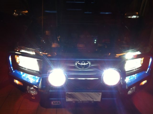
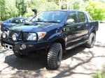
It's an SR5, I took the orig fogs & remounted them in the ARB deluxe bar.
Not sure if I will change the fogs to HID spots, still deciding.
- fredbear
- Posts: 150
- Joined: Wed, 19 Nov 2008 9:56 +0000
- Location: SA
Re: Fred's build.
![]() by packeteer on Mon, 17 Sep 2012 9:50 +0000
by packeteer on Mon, 17 Sep 2012 9:50 +0000
I'm so going to do this. Will be much nicer than the mess the auto sparky made!
-

packeteer - Posts: 3468
- Joined: Wed, 27 Apr 2011 1:49 +0000
- Location: Chatswood, Sydney
Re: Fred's build.
![]() by Aquaholics on Wed, 19 Sep 2012 6:06 +0000
by Aquaholics on Wed, 19 Sep 2012 6:06 +0000
fredbear wrote:All went OK in a straight line and seemed OK when I turned, but just as I went over the small dip into the garage with about 1/2 lock on I heard something. I think the tyre touched the mudflap, but I couldn't see any marks when I looked.
Hi Fred,
So you have been running around in the new shoes for two weeks now, interested to hear how you are finding them?
-
Aquaholics - Posts: 226
- Joined: Mon, 27 Aug 2012 4:25 +0000
- Location: Lake Macquarie - Newcastle
Re: Fred's build.
![]() by fredbear on Wed, 19 Sep 2012 12:08 +0000
by fredbear on Wed, 19 Sep 2012 12:08 +0000
Aquaholics wrote:
Hi Fred,
So you have been running around in the new shoes for two weeks now, interested to hear how you are finding them?
MTZ's are good, little bit of rain we have had and they don't slip (like I find the originals do, hence I changed them over from new).
For the moment I have taken the front mudflaps off....BUT a box from Monster arrived this morning....I'll hit the shed after work & fix the rubbing
- fredbear
- Posts: 150
- Joined: Wed, 19 Nov 2008 9:56 +0000
- Location: SA
Re: Fred's build - Monster Ride Installed
![]() by fredbear on Tue, 25 Sep 2012 8:54 +0000
by fredbear on Tue, 25 Sep 2012 8:54 +0000
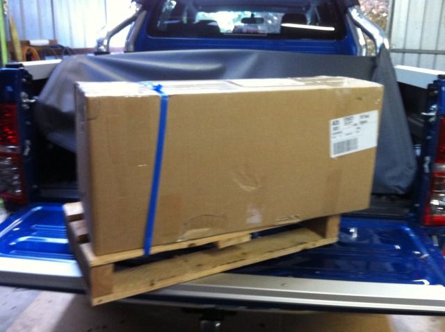
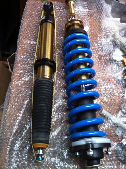
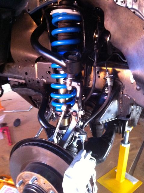
Well it took me a couple of days to get it done but I now have the Monster Stage 2 installed.
It took me a while to figure out the steps to get it done, so first side was slow (3+ hrs) the second was 40 mins!
But then I had to wait an extra day as Matty sent me some updated struts which seem very nice
So for those about to do the install here are some gotchas so hopefully you can do it in 40 mins also!.
Here are the steps I suggest in order. BTW I'm not a qualified mechanic, so the following are suggestions only, please see a qualified Mechanic if your not sure of your abilities. I started on the Drivers side first.
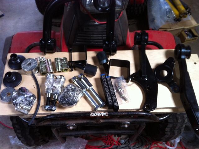
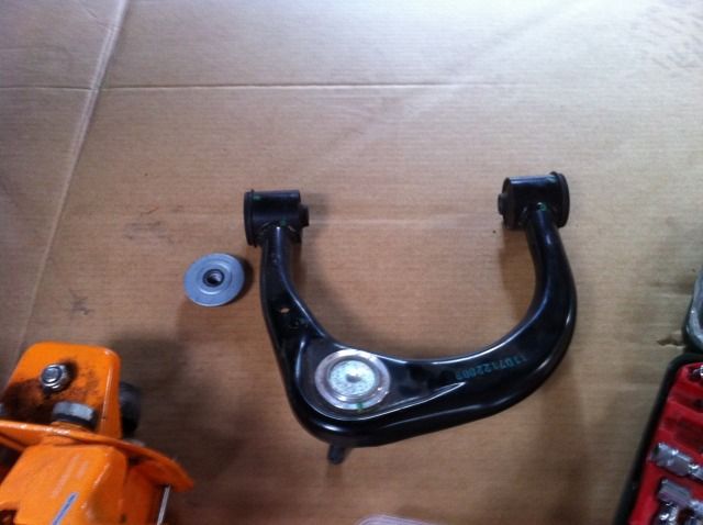
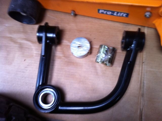
1. This is what arrived (no bash plates as yet)
2. So here are the bits in addition to the front & rear shocks.
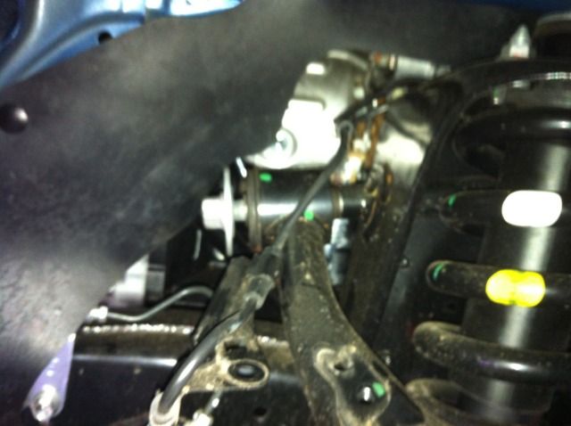
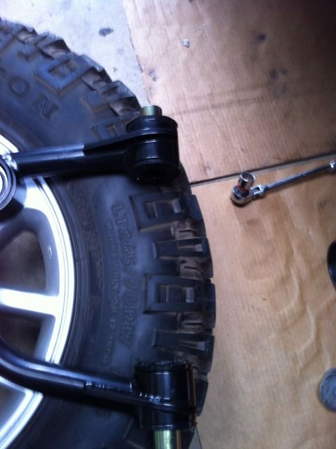
3. First step - Remove this bolt that holds the front of aircleaner - the air cleaner is in the way when removing the UCA bolt.
4. Disconnect Sway bar link & undo front bolts
5. The plate bolts in using original bolts, then the swaybar bracket bolts to the plate with MR supplied bolts
Don't reconnect the link yet. Put the plate in on other side.
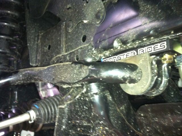
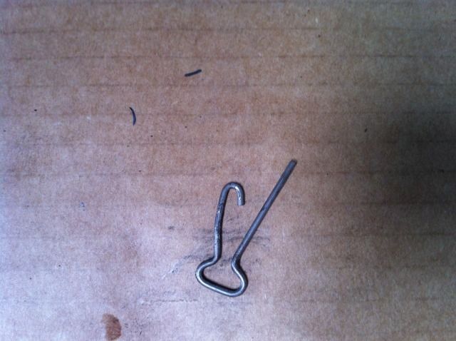
6. Remove this pin/clip
7. and loosen (but don't remove) the UCA to upright nut. Then hit front flat area of upright with a 4lb hammer a couple of times & the joint should pop apart.
8. Support the disc etc with a jack & remove the nut.
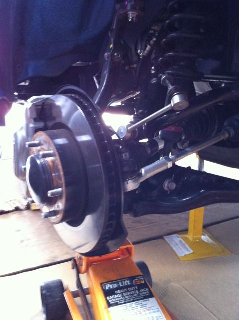
9. Sorry for poor pic, but I removed the 3 bolts that hold the brake/ABS hoses in place, this gives a bit more flex in the lines.
10. I used a bit of fencing wire to help support it all while I removed the UCA.
11. Undo the nut on the UCA and slide the bolt out. You will need to lift the aircleaner up a little to get the bolt out. I started under the vehicle then got the last section out from under the bonnet (had to stand on steps as vehicle was on stands)
It took me a while to figure out the steps to get it done, so first side was slow (3+ hrs) the second was 40 mins!
But then I had to wait an extra day as Matty sent me some updated struts which seem very nice
So for those about to do the install here are some gotchas so hopefully you can do it in 40 mins also!.
Here are the steps I suggest in order. BTW I'm not a qualified mechanic, so the following are suggestions only, please see a qualified Mechanic if your not sure of your abilities. I started on the Drivers side first.
1. This is what arrived (no bash plates as yet)
2. So here are the bits in addition to the front & rear shocks.
3. First step - Remove this bolt that holds the front of aircleaner - the air cleaner is in the way when removing the UCA bolt.
4. Disconnect Sway bar link & undo front bolts
5. The plate bolts in using original bolts, then the swaybar bracket bolts to the plate with MR supplied bolts
Don't reconnect the link yet. Put the plate in on other side.
6. Remove this pin/clip
7. and loosen (but don't remove) the UCA to upright nut. Then hit front flat area of upright with a 4lb hammer a couple of times & the joint should pop apart.
8. Support the disc etc with a jack & remove the nut.
9. Sorry for poor pic, but I removed the 3 bolts that hold the brake/ABS hoses in place, this gives a bit more flex in the lines.
10. I used a bit of fencing wire to help support it all while I removed the UCA.
11. Undo the nut on the UCA and slide the bolt out. You will need to lift the aircleaner up a little to get the bolt out. I started under the vehicle then got the last section out from under the bonnet (had to stand on steps as vehicle was on stands)
Last edited by fredbear on Tue, 25 Sep 2012 9:50 +0000, edited 2 times in total.
- fredbear
- Posts: 150
- Joined: Wed, 19 Nov 2008 9:56 +0000
- Location: SA
Re: Fred's build - Monster Ride Installed
![]() by fredbear on Tue, 25 Sep 2012 9:22 +0000
by fredbear on Tue, 25 Sep 2012 9:22 +0000
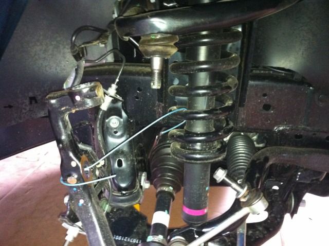
12. Install 2 of the metal spaces, be careful not to bend the UCA as you tap them in .
13. Then Grab the packet of 8x big washers. 4 go like this
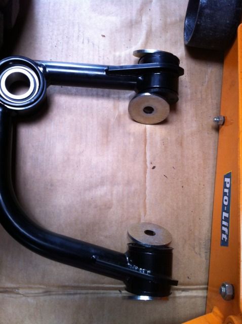
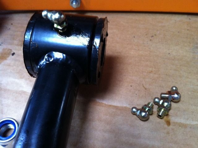
14. And put in the grease nipples. (9mm spanner needed)
15. You should be able to start the bolt while working under the guard. You need about 3 hands (?) but you will prob have to lift the aircleaner a little again to get the bolt through.
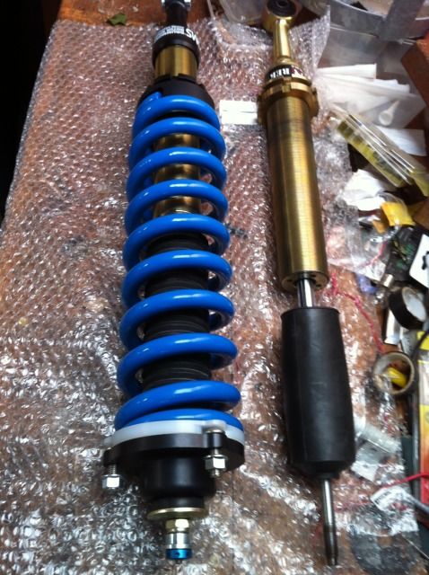
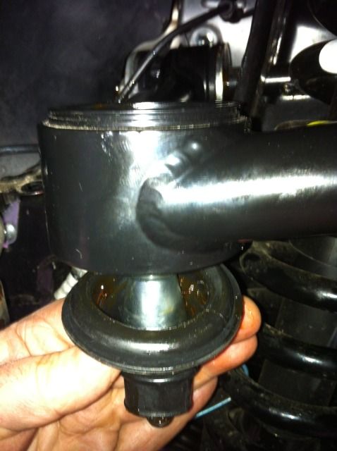
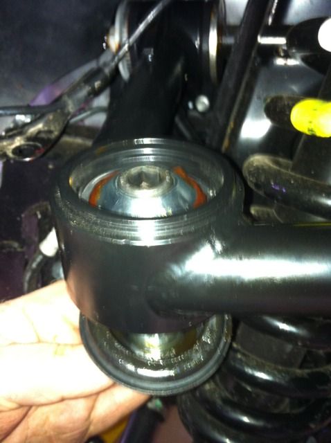
16. I actually installed the balljoint shaft at this point, but when I did other side I worked on the strut first, which worked out better. So here are my "OLD" new struts and the NEW NEW adjustable ones Matty sent me. Just had to move the springs & top hats over.
17. Top hats come of easy and as the springs are adjustable there is no dangerous spring tension to worry about here. (I have left the original toyota struts as assembled units as I don't have tools to dismantle them I paid Matty for the new top hats. )
18. Now unless you have arms like a gorrilla I doubt you will compress the shock (not the spring, just the shock) enough to get the huge length in. I struggled until I used my brain instead of trying braun. The first method I tried was to loosely put the top in position to hold it, then I used a ratchet strap to compress the shock (not the spring as it is still all loose & not under tension). Once compressed I used some packing strapping to hold it in place.
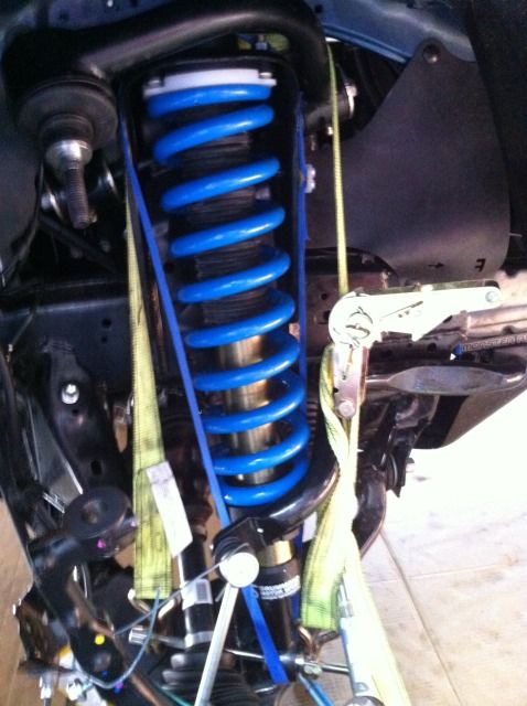
19. And it slipped in easily.
20. Bolt in, undo the packing strap & save this magic stuff for another day
21. For the other side I had a 2nd & I think better idea. Instead of putting it in the vehicle I did it on the bench, actually under the bench. This worked great. I had the spring loosened off all the way, and compressed the shock with the jack until it started to act on the spring, & I packing strapped it into place.
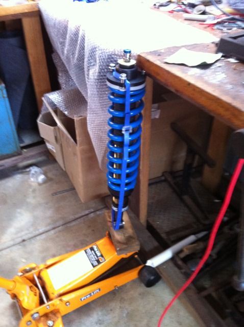
(I took this pic a bit earlier, the spring base is not undone all the way, and therefore the whole shock is still to long, I redid it under the bench again just after the pic was taken.
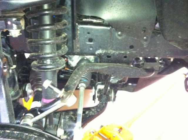
22. This pic is the left side in. Note the brake hose mounts are all undone.
23. Assemble the rubber boot on the shaft like this.
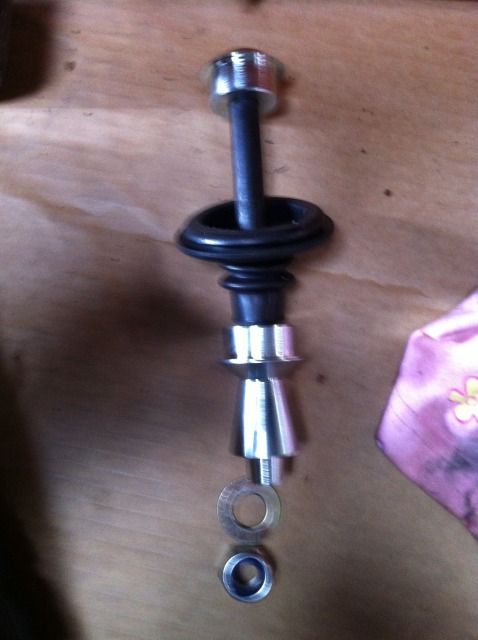
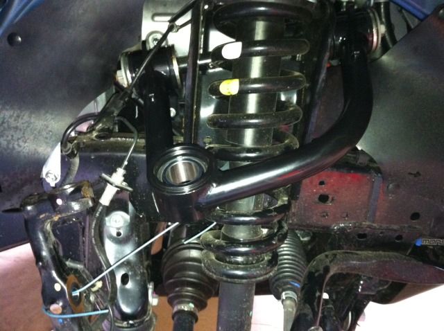
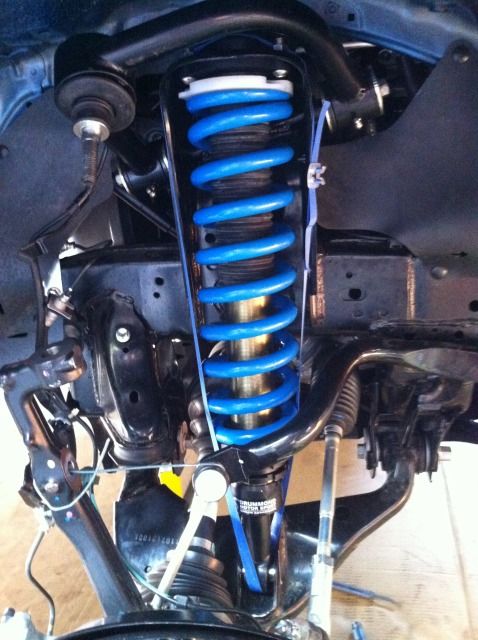
24. And fit it into the UCA.
25. Reconnect the Upright (pic has swaybar reconnected - this was a mistake & I had to undo it again)
26. Reconnect the brake mounts etc. Don't reconnect the Sway bar just yet.
13. Then Grab the packet of 8x big washers. 4 go like this
14. And put in the grease nipples. (9mm spanner needed)
15. You should be able to start the bolt while working under the guard. You need about 3 hands (?) but you will prob have to lift the aircleaner a little again to get the bolt through.
16. I actually installed the balljoint shaft at this point, but when I did other side I worked on the strut first, which worked out better. So here are my "OLD" new struts and the NEW NEW adjustable ones Matty sent me. Just had to move the springs & top hats over.
17. Top hats come of easy and as the springs are adjustable there is no dangerous spring tension to worry about here. (I have left the original toyota struts as assembled units as I don't have tools to dismantle them I paid Matty for the new top hats. )
18. Now unless you have arms like a gorrilla I doubt you will compress the shock (not the spring, just the shock) enough to get the huge length in. I struggled until I used my brain instead of trying braun. The first method I tried was to loosely put the top in position to hold it, then I used a ratchet strap to compress the shock (not the spring as it is still all loose & not under tension). Once compressed I used some packing strapping to hold it in place.
19. And it slipped in easily.
20. Bolt in, undo the packing strap & save this magic stuff for another day
21. For the other side I had a 2nd & I think better idea. Instead of putting it in the vehicle I did it on the bench, actually under the bench. This worked great. I had the spring loosened off all the way, and compressed the shock with the jack until it started to act on the spring, & I packing strapped it into place.
(I took this pic a bit earlier, the spring base is not undone all the way, and therefore the whole shock is still to long, I redid it under the bench again just after the pic was taken.
22. This pic is the left side in. Note the brake hose mounts are all undone.
23. Assemble the rubber boot on the shaft like this.
24. And fit it into the UCA.
25. Reconnect the Upright (pic has swaybar reconnected - this was a mistake & I had to undo it again)
26. Reconnect the brake mounts etc. Don't reconnect the Sway bar just yet.
Last edited by fredbear on Tue, 25 Sep 2012 9:55 +0000, edited 2 times in total.
- fredbear
- Posts: 150
- Joined: Wed, 19 Nov 2008 9:56 +0000
- Location: SA
Re: Fred's build - Monster Ride Installed
![]() by fredbear on Tue, 25 Sep 2012 9:48 +0000
by fredbear on Tue, 25 Sep 2012 9:48 +0000
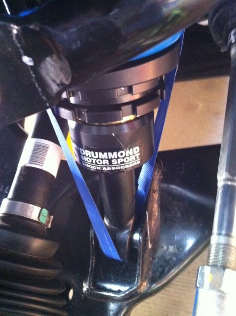
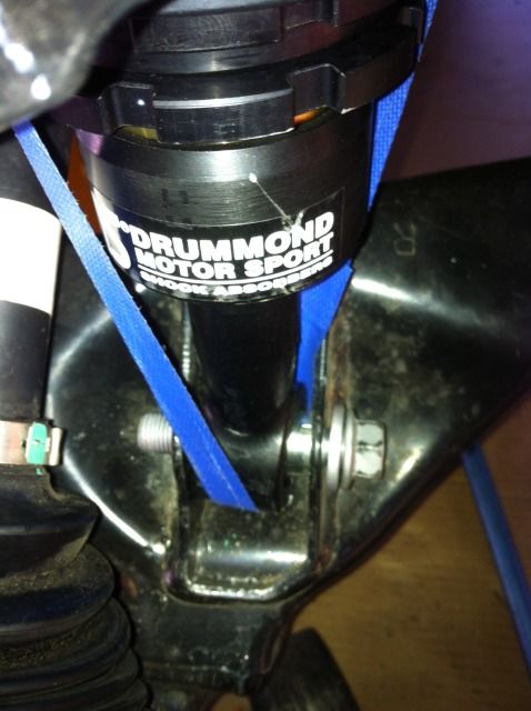
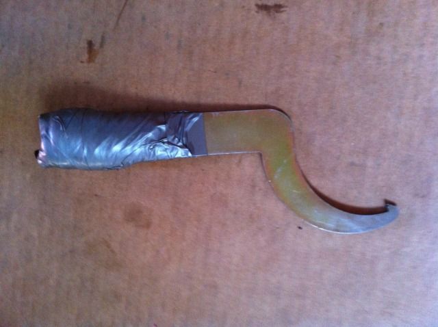
I already mentioned the 9mm spanner for the grease nipples, but you will prob need these. I used the HEX ones on the UCA bolt and also for the Bump stops (Extra cost to Stage 2 kit if I remember correctly). The Stilsons are to get the original Toyota bumps undone. They are tight but just unscrew.. On the new bumps, don't forget the washer.
original bump stop.
I just mentioned not putting sway bar links in just yet. The reason is the sway bar gets in the way of winding up the struts.
I initially had the wishbone on full droop (without swaybar) and wound the nut up to just touch the spring on each side.
Then I added 5 full revolutions more. I then put wheels on and did some measurements.
I left the wheels on and jacked up the hilux & did my extra turns to get the height I wanted. The C spanner is a bit hard/sharp on the hands so I used bubble wrap & duct tape. (I'm not a gorilla remember!)
The other thing I noticed was the whole spring spins as I wound up the base nut. So to help this I sprayed some WD40 in the top of the spring so it would spin a little easier.
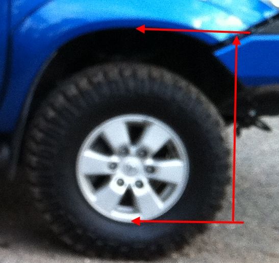
I set the drivers side to 800mm and the passenger side to 795. this is about 60mm up on original measurements.
I then installed the 3 brackets to lower the diff. This has been documented by others. eg here viewtopic.php?t=13377 Fairly straight forward, other than getting some of the bolts back in. I had to try doing them in several different orders on each plate to get them all started.
Still waiting on the bash plates to arrive and the UCA uni - joint protectors.
I'll drive it tomorrow, readjust the heights tomorrow night then book a wheel alignment for thurs...pack on friday and long weekend off - so flinders here we come, the long way around.
AMENDMENT: Adjustment.
So I drove for a day and tonight did some re adjustments.
The initial setting on the struts was to low. I was looking for ~60mm lift.
The c spanner is a PITA ( do snap-on or some one make a ratchet version?)
I removed the Swaybar to make it easier to adjust.
While adjusting I wanted to a) figure out how many turns = how much lift, and b) how to replicate on other side.
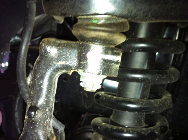
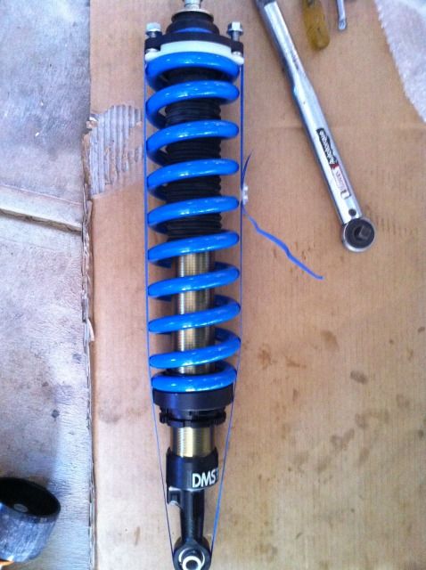
So I took a measurement with vernier calipers between the underside of the adjusting nut and the top of the base. (see pic)
Ignore the lock nut, just undo it several turns to get it out of the way while you measure. (This was a prev pic I just marked up to illustrate my measurement method)
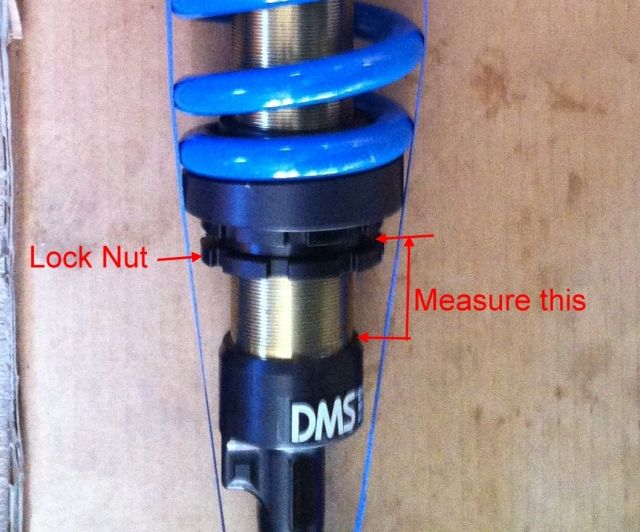
Eventually I ended up with 76mm on drivers side and 75mm on passenger side on above measurement. At this point the nut was fairly tight to turn.
This gave me 800mm from inside bottom edge of rim to flare on drivers side and 795mm on passenger side. Which is ~60mm above std.
I then stuffed my CV boots (Note to self: NEVER forget to reattach sway bar!) so limped back to shed & parked it. Adjustment on hold for now.
original bump stop.
I just mentioned not putting sway bar links in just yet. The reason is the sway bar gets in the way of winding up the struts.
I initially had the wishbone on full droop (without swaybar) and wound the nut up to just touch the spring on each side.
Then I added 5 full revolutions more. I then put wheels on and did some measurements.
I left the wheels on and jacked up the hilux & did my extra turns to get the height I wanted. The C spanner is a bit hard/sharp on the hands so I used bubble wrap & duct tape. (I'm not a gorilla remember!)
The other thing I noticed was the whole spring spins as I wound up the base nut. So to help this I sprayed some WD40 in the top of the spring so it would spin a little easier.
I set the drivers side to 800mm and the passenger side to 795. this is about 60mm up on original measurements.
I then installed the 3 brackets to lower the diff. This has been documented by others. eg here viewtopic.php?t=13377 Fairly straight forward, other than getting some of the bolts back in. I had to try doing them in several different orders on each plate to get them all started.
Still waiting on the bash plates to arrive and the UCA uni - joint protectors.
I'll drive it tomorrow, readjust the heights tomorrow night then book a wheel alignment for thurs...pack on friday and long weekend off - so flinders here we come, the long way around.
AMENDMENT: Adjustment.
So I drove for a day and tonight did some re adjustments.
The initial setting on the struts was to low. I was looking for ~60mm lift.
The c spanner is a PITA ( do snap-on or some one make a ratchet version?)
I removed the Swaybar to make it easier to adjust.
While adjusting I wanted to a) figure out how many turns = how much lift, and b) how to replicate on other side.
So I took a measurement with vernier calipers between the underside of the adjusting nut and the top of the base. (see pic)
Ignore the lock nut, just undo it several turns to get it out of the way while you measure. (This was a prev pic I just marked up to illustrate my measurement method)
Eventually I ended up with 76mm on drivers side and 75mm on passenger side on above measurement. At this point the nut was fairly tight to turn.
This gave me 800mm from inside bottom edge of rim to flare on drivers side and 795mm on passenger side. Which is ~60mm above std.
I then stuffed my CV boots (Note to self: NEVER forget to reattach sway bar!) so limped back to shed & parked it. Adjustment on hold for now.
Last edited by fredbear on Wed, 26 Sep 2012 9:18 +0000, edited 3 times in total.
- fredbear
- Posts: 150
- Joined: Wed, 19 Nov 2008 9:56 +0000
- Location: SA
Re: Fred's build - Monster Ride Installed
![]() by 10 luxxxx on Wed, 26 Sep 2012 12:21 +0000
by 10 luxxxx on Wed, 26 Sep 2012 12:21 +0000
Awesome write up mate nice work
VIEW MY BUILD viewtopic.php?f=41&t=14606
-
10 luxxxx - Posts: 1507
- Joined: Mon, 19 Dec 2011 12:37 +0000
- Location: Perth
Re: Fred's build - Monster Ride Installed
![]() by Loosey on Wed, 26 Sep 2012 3:03 +0000
by Loosey on Wed, 26 Sep 2012 3:03 +0000
10 luxxxx wrote:Awesome write up mate nice work
Agreed, always very informative!
-
Loosey - Posts: 2391
- Joined: Sat, 18 Aug 2012 2:55 +0000
- Location: Newcastle
Re: Fred's build - Monster Ride Installed
![]() by shanno on Wed, 26 Sep 2012 4:01 +0000
by shanno on Wed, 26 Sep 2012 4:01 +0000
Nice write up mate! Will be good to hear your thoughts on the Adjustable shocks after you've clocked up some ks on them
-
shanno - Posts: 570
- Joined: Wed, 12 May 2010 6:33 +0000
- Location: Tieri, QLD
Who is online
Users browsing this forum: No registered users and 71 guests
![]()