Disassembly process.
Important safety notes:
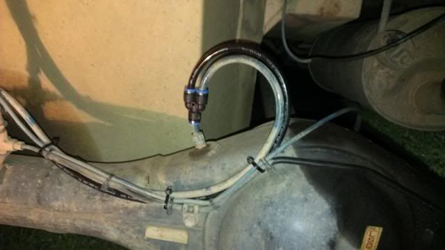
Wear safety goggles and discharge accumulator on the compressor using tyre deflator or other method to relieve pressure in unit.
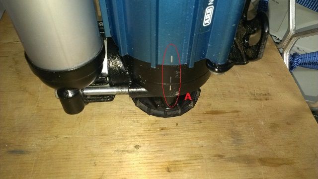
Step 1: See photo above. Witness mark one end of the frame of the motor to aid in reassembly.
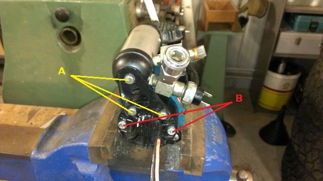
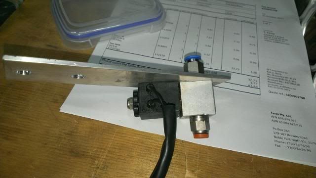
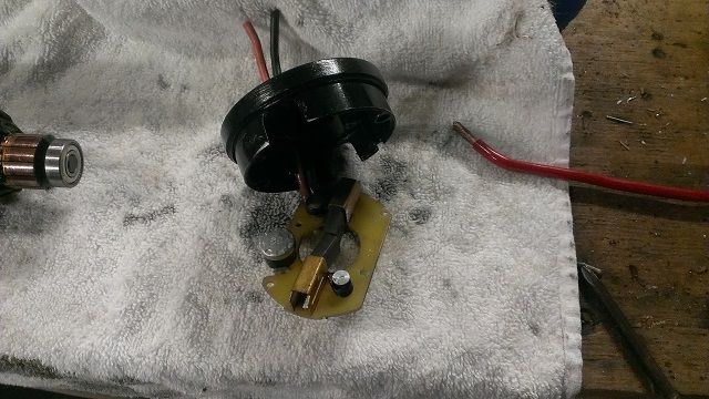
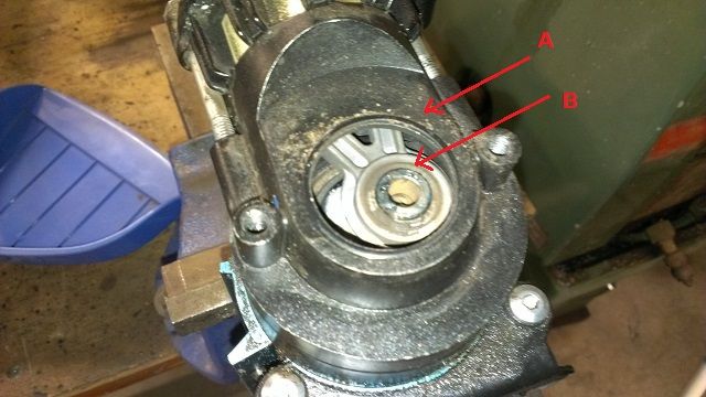
Step 2: See photo above. Remove 3off X 10mm head bolts (marked A), bracket holding receiver along with the receiver will disassemble. Be careful to not lose or damage the seals.
Step 3. Unbolt and remove 2 off end cap bolts (marked B). Compressor and brush ends can be removed from the frame of the motor.
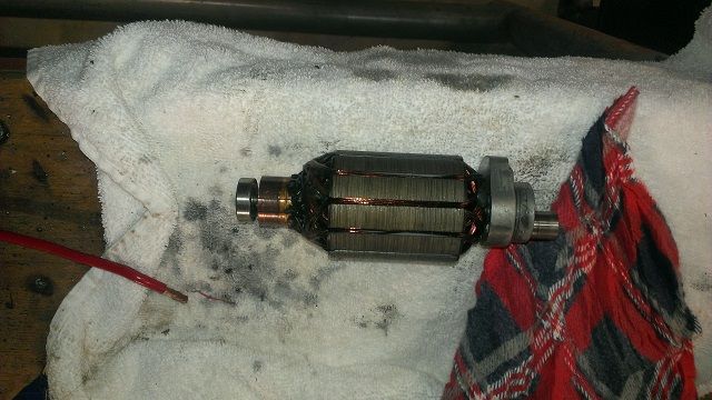
Step 4. See Above. Armature can be removed from frame for inspection.
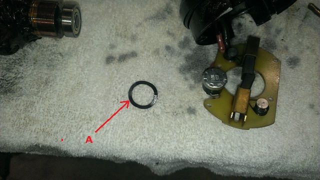
Belvere washer marked A above.
Step 5. (Optional) See Above. Remove all Phillips head screws from brush end and remove brush assembly from end cap. Ensure that you do not lose the Belvere washer that is located in bearing end.
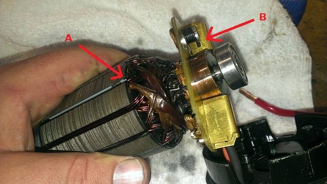
Step 6: See above. Clean armature and brush assembly with contact cleaner. Inspect armature, stator brushes and bearings for wear. Armature is marked A and brush assembly B
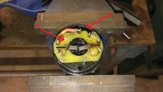
Step 7: See above. Place brush end cap in Vice (marked B) Using Phillips screws re assemble brush pack back into bearing cap (marked A).
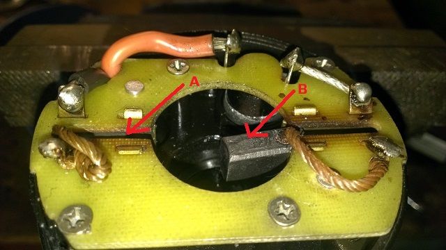
A= brush pushed back: B brush still forward position
Ready for stator and armature to be dropped back into cap.
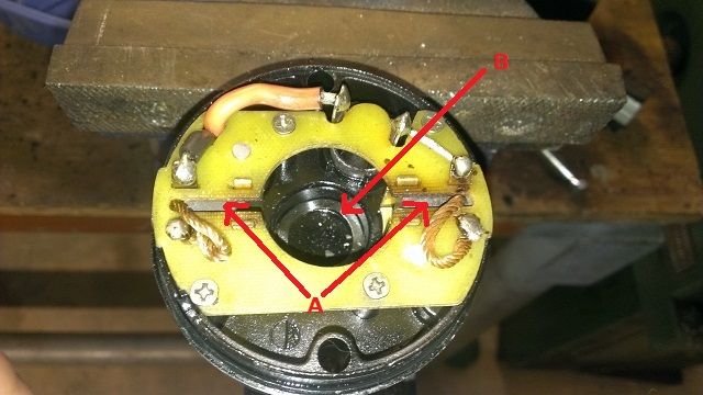
A= brushes pushed back B= Belvere washer installed into bearing cap
Step 8: See above. Push bushes back until they lock into back postion and make sure that Belver washer is inserted back into bottom of bearing cap.

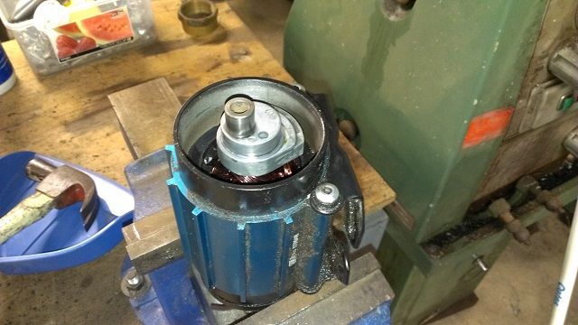
Step 9: See above. A= motor frame, B= armature.
Insert armature back into frame of the motor. The magnetic field will drag the armature back into the frame. Ensure that it is re assembled to correspond to the witness marks. (ie. Piston end has crankshaft poking out and not stator.)
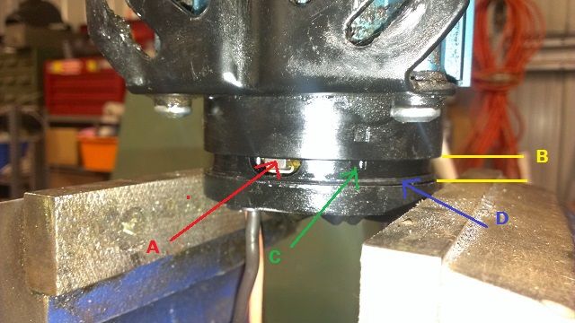
Step 10: Lower assembled armature and motor frame down onto bearing cap. Make sure that O ring is in and alignment mark are clocked correctly. Insert a small wedge so that it maintains a 3-5mm gap between the faces.
A= Exposed brush, B= Gap between faces, C= alignment lug, D= O ring
Step 11. Using a small screwdriver or rod, push the back of the brush A (Exposed brush) with light pressure to get it to click back onto the stator. You will hear a small click as the brush snaps back on to the stator. Make sure that you do both brushes. Once both brushes have been snapped back onto the stator, remove the wedge and allow the frame to rest back onto the O ring. You will have to start back again at Step8 if the frame and armature drop off the brushes on the Stator.
(pic to be added)
Step 12. See above.Remove intake filter and adaptor plate from the compressor section of the motor
Step 13. Apply a small dob of grease to the big end bearing and running surface on end of crankshaft.
Step 14: Carefully align conrod back (marked A) onto bigend (marked B) and lightly push back together.
Step 15: See above. Insert long frame bolts back through brush end and tighten (marked B). Carefully install receiver tube, bracket and bolts (marked A). Tighten carefully to not pinch seals.
(pic to be added)
Step 16: Re assemble adaptor plate and filter back on compressor end.
Step 17: Connect compressor to 12v DC and see if it operates. If it doesn’t you may not have clicked in a brush properly or forgotten to do Step 11. To rectify this remove all 5 bolts on the back of the bearing/ brush cap and try to pull it back to expose the brushes again. With a small screw driver click the brushes back onto the stator. You may have to disassemble and start again back at Step 7 if the brushes pop off the stator.