Front CV Maximum Angles

Gearboxs, Transfers, Tailshafts, Diffs, axles and CVs

Front CV Maximum Angles

Postby superclarkey on Fri, 15 Dec 2023 11:46 +0000

I have done some searching on this but comes up with allot of random speculations, so if there is a thread I've missed please direct me there :)

I want to know what the maximum CV angles are for the front drive half shafts are, inner and outer.

The reason I want to know this is because I want to know what safe amount of droop I can add to the suspension (coilover spacer) before the shafts start to contact the housings. Note that full droop the wheels is most likely off the ground or in a very low traction situation, so pressure on the CV should be low at the max extreme, this is more that it doesn't yank the inner. (Clearly as soon as I limit the ball joints out of the UCA then that is its maximum droop).

I've looked on the GKN website and I got this about the inner CV.

I think the inner is this type - Tripod Plunging (AAR) Joint

In addition to the properties of the GI joint, the low plunging resistance and low axial forces of the AAR joint deliver additional NVH refinement, making it appropriate for high working angles. It has a maximum articulation angle of 26 degrees and 50mm plunge.


If that is true 26° is allot, as I'm currently measuring only 18.8° at full droop. (7.2° left of safety).

The outer CV joint I'm not sure, but I'm guessing it's the 50°versions? clearly this has steering to deal with also so true working angle is a combination of steering angle and shaft angle etc.

I've ordered a Kaon diff drop kit, which is in UK customs at the moment so not got my hands on it.

Now I know allot of times people ask how far can I lift my truck and that is when CV angles suffer as they are operating at this extra height at all the time, but this is not what I'm after here, I'm happy to run a 40mm lift but I'm just trying to gain as much articulation as possible. I want to add a spacer at the top of the BP-51 to push shock down, and trade that for shock compression so I'm not so close to topping the coilover out. Currently 9mm away from stops with 10mm preload!

When the diff drop arrives I plan to strip the BP-51 down and do some accurate measurements, as I have a feeling the BP-51 shock is kinda short but without knowing what other brands do I can only go off what the OEM shock length is.

Be interested to know what people know or what they have learnt by going to far etc.
superclarkey
 
Posts: 71
Joined: Tue, 06 Dec 2022 11:53 +0000
Location: England


Re: Front CV Maximum Angles

Postby hiluxxury on Wed, 20 Dec 2023 4:30 +0000

I don't have an angle for you but the tripod will bind when you've gone too far. I drove for years with tripod bind that I could feel through the steering wheel - was a known risk for me and I drove accordingly. It's easy to test by jacking the car up to get full droop and testing if you can turn a front wheel by hand. If you can feel three distinct points of resistance in a wheel rotation, that's the tripod beginning to bind. If you can't turn the wheel by hand, the tripod is binding.

I don't think there's much more CV suffering/wear when the CVs aren't straight, they are just slightly weaker.

Be careful with spacers or you'll bend the strut without a lengthened bump stop. You'll only get about 27 to 30cm of travel out of the stock arms and CVs. My view is that's plenty for the Hilux. If you want the front to flex/work better, stiffen the rear springs or drop the front sway bar (illegal). If you are chasing traction get lockers.
I might be wrong.

2005 SR Hilux 1KD - SOLD
2009 BMW X5 - destroyed by a hail storm
2012 Range Rover Sport SDV6 - SOLD
2015 Ford Ranger
User avatar
hiluxxury
Moderator
 
Posts: 1584
Joined: Sun, 20 Dec 2009 4:16 +0000
Location: Tasmania

Re: Front CV Maximum Angles

Postby superclarkey on Thu, 21 Dec 2023 5:38 +0000

hiluxxury wrote:I don't have an angle for you but the tripod will bind when you've gone too far. I drove for years with tripod bind that I could feel through the steering wheel - was a known risk for me and I drove accordingly. It's easy to test by jacking the car up to get full droop and testing if you can turn a front wheel by hand. If you can feel three distinct points of resistance in a wheel rotation, that's the tripod beginning to bind. If you can't turn the wheel by hand, the tripod is binding.

I don't think there's much more CV suffering/wear when the CVs aren't straight, they are just slightly weaker.

Be careful with spacers or you'll bend the strut without a lengthened bump stop. You'll only get about 27 to 30cm of travel out of the stock arms and CVs. My view is that's plenty for the Hilux. If you want the front to flex/work better, stiffen the rear springs or drop the front sway bar (illegal). If you are chasing traction get lockers.


First things first, thanks for the reply :) I was almost thinking no one would ever reply to my question haha.

The tripods I was more worried about them popping out than binding, but if they do I presume it will the shaft contacting the outer race, so maybe that is easy fix to add some relief. I'm presuming alignment will make a difference also, depending if lower arm is fully in or fully out.

I'm interested to know more one about what causes shocks to bend with spacers?

Thanks
superclarkey
 
Posts: 71
Joined: Tue, 06 Dec 2022 11:53 +0000
Location: England

Re: Front CV Maximum Angles

Postby superclarkey on Thu, 21 Dec 2023 7:19 +0000

This is a series of photos to help explain what I'm trying to do with adding a spacer to the top of the shock and trading it for shock travel.

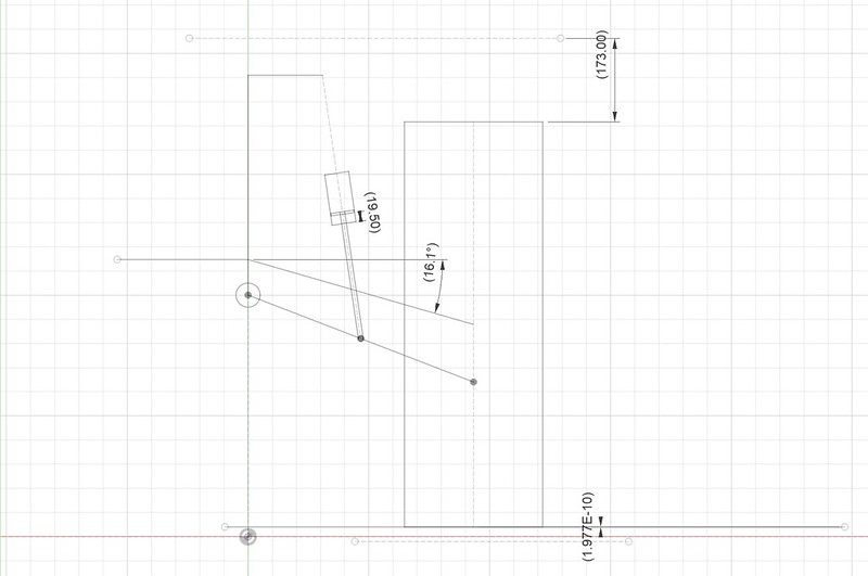
To explain the diagram and what your looking at.. The rectangle is the tyre, and the 173mm from the top of the tyre to the dotted line, is the arch gap. Where the 9.50mm is the shock, to simplify it just is attached to the lower arm and chassis via the dotted line, you can see the piston inside the shock. The angle is the driveshaft angle.

So this first image is "as is" now, when the weight of the vehicle, as you can see with the weight of the vehicle fully loaded the suspension moves down 9.5mm of the travel of the shaft, total is 100mm. As you'll see in the next photo, when fully drooped (all weight off and the shock at 0mm travel), which is 20mm down travel at the wheel, this shows there is a motion ratio of around 0.5.

Image

Hopefully you can see the wheel has moved down 20.365mm, and the shock is fully topped out.

Image

Suspension fully compressed, at 100mm shock travel. (note this isn't taking into spring bind, or lower arm hitting bump stop.. I'm fairly sure the bump stop will come first but need to measure this).

Image

So in summary, in the stock position the following is true.

Wheel
Droop = 20.4mm
Compression = 189.8mm
Total Travel = 210.2mm

Shock
Stroke at ride height - 9.5mm out of 100mm (9.5% of shock travel).

The main point here is that your only 9.5mm down the shock travel, which is 20mm at the wheel.. as you drive down the road the wheel dropping away from vehicle more than 20mm will top out the shock, now imagine your going round a corner and the vehicle is leaning over, that 20 mm could be more like 10-0mm causing harsh ride and bad handling.

Also worth mentioning (and I don't know it to be a fact with the BP-51) but normally shocks close to the topping out have a high resistance zone to dampen the shock from crashing out, so running so close could actually cause the shock to give a horrible ride. Normally we aim to be sitting 1/3 of the shock travel at ride height for comfort.

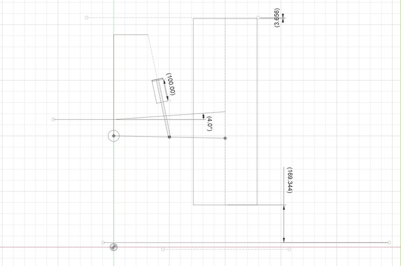
Okey, so this is now the same 3 photos (well in order as above) but with a 10mm spacer added between the top of the shock and chassis, spacing the whole assembly down. SO it will add 10mm at the top, and will be 20mm at the wheel. (So will lift the vehicle).

So should go without saying that adding the 10mm spacer at the top, will not change the travel down the shock as the same preload is holding the vehicle up.

Image

So at fully droop.. the same amount however as the starting position is 20mm down to start with, it's now 40mm. (This is where shaft angle is asking for trouble).

Image

At 100mm shock position, you can see the wheel doesn't go higher than the arch now, its 3.7mm below (Again might not even get this high due to the stop).

Image

So this doesn't help the shock position, as I'm still at 9.5mm down the travel. As expected its just moved the whole travel down by 10mm at the shock and 20mm at the wheel.

Wheel
Droop = 41.8mmm
Compression = 169.3mm
Total Travel = 211.1mm

Shock
Stroke at ride height - 9.5mm out of 100mm (9.5% of shock travel).

Okey, so guess to get to the point lol.. This is with 10mm spacer as previous but now reducing the preload by 10mm. The shock is currently at +10mm preload setting, so when I say reducing by 10mm, i.e setting it to zero or fully wound off.

So you'll see the shock is 19.50mm down the shaft now, which is getting closer to where I want to be, ideally 33mm down (33%, or 1/3), but much better then where I'm currently sitting. You'll also see that adding the spacer and removing 10mm preload has cancelled out, so the ride height is same first set of 3 photos, however so no lift, but I've traded the lift for shaft travel.

The difference you'll notice is, the shock now has more droop.. and the shock doesn't have the travel it had before.. but again if the bump stops or coil bind happens first.. I'm bring some shock travel into play that would normally be out of reach.

Image

Fully Droop (Same as 10mm spacer alone with no preload) this is the most dangerous consequence of the mod.

Image

Full compression, notice same 3.7mm to fender.

Image

Wheel
Droop = 41.8mmm
Compression = 169.3mm
Total Travel = 211.1mm

Shock
Stroke at ride height - 19.5mm out of 100mm (19.5% of shock travel).

Summary

Adding a 10mm spacer, and removing 10mm preload, perfectly canceled out and doesn't change ride height.. however what it does is moves the position of the shaft and allows more downward travel, which is traded for compression.. however as I'm sure would never get full travel before coil bind or lower arm hitting the bump stop, this is part of the shock that is normally not used.

I know this is very long winded.. but I thought best to be detailed and not leave it open to misunderstanding and better to explain it fully.

My under standing that fitting 35mm spacers to gain lift is where the issues lies and why people think they are bad and to be avoided. but that is a 65-70mm lift so that is the issue and causing ball joints to bind.

Hopefully you'll understand why I need to give the shock more than 9.5mm of travel at ride height. IF I want to lift the truck further than this I would add more spacers maybe upto 15mm tops.. but I'm going to see what angles of the shafts cause an issue.. again getting a proper diff drop is the key to this without causing major issues.

I also want to install limiting straps on the front to protect the shocks topping out.

Let me know your thoughts :) IF you make it to the end of all this, you've my kind of person :)
superclarkey
 
Posts: 71
Joined: Tue, 06 Dec 2022 11:53 +0000
Location: England

Re: Front CV Maximum Angles

Postby hiluxxury on Fri, 22 Dec 2023 12:45 +0000

superclarkey wrote:
I'm interested to know more one about what causes shocks to bend with spacers?

Thanks


The strut length becomes too long causing the strut to become the bumpstop. So you either bend the strut or the top strut mount.
I might be wrong.

2005 SR Hilux 1KD - SOLD
2009 BMW X5 - destroyed by a hail storm
2012 Range Rover Sport SDV6 - SOLD
2015 Ford Ranger
User avatar
hiluxxury
Moderator
 
Posts: 1584
Joined: Sun, 20 Dec 2009 4:16 +0000
Location: Tasmania

Re: Front CV Maximum Angles

Postby superclarkey on Sat, 23 Dec 2023 2:06 +0000

hiluxxury wrote:
superclarkey wrote:
I'm interested to know more one about what causes shocks to bend with spacers?

Thanks


The strut length becomes too long causing the strut to become the bumpstop. So you either bend the strut or the top strut mount.


I thought it might be this, but I also thought it could be the UCA hitting the shock at full extension. Makes sense though as the shock shouldn't be the bump stop!
superclarkey
 
Posts: 71
Joined: Tue, 06 Dec 2022 11:53 +0000
Location: England

Re: Front CV Maximum Angles

Postby hiluxxury on Sun, 24 Dec 2023 3:04 +0000

Some people extended the bumpstop but you've gotta wonder why go to all that trouble when you can just install the correct strut and spring combo
I might be wrong.

2005 SR Hilux 1KD - SOLD
2009 BMW X5 - destroyed by a hail storm
2012 Range Rover Sport SDV6 - SOLD
2015 Ford Ranger
User avatar
hiluxxury
Moderator
 
Posts: 1584
Joined: Sun, 20 Dec 2009 4:16 +0000
Location: Tasmania

Re: Front CV Maximum Angles

Postby superclarkey on Mon, 25 Dec 2023 6:11 +0000

hiluxxury wrote:Some people extended the bumpstop but you've gotta wonder why go to all that trouble when you can just install the correct strut and spring combo


I think the bump stop will still be fine for only a 10-15mm spacer, specially as this shock seems fairly short (or on the safe side), but yes it would be nice to have a system that just works or is correct first time round. In the UK the options are very limited on what I can purchase and the BP-51 seemed to fit the bill, as everyone seems to give glowing reviews.

I will hold my judgement until I use them properly :)

At the moment, I'm just trying to optimise the setup best I can, then if it all works I can share what I've learnt with others.
superclarkey
 
Posts: 71
Joined: Tue, 06 Dec 2022 11:53 +0000
Location: England

Re: Front CV Maximum Angles

Postby Chopps on Tue, 26 Dec 2023 6:15 +0000

Are you referring a top strut spacer?
Those spacers are fine for going to the shops but if taken offroad on any decent 4X4 track expect a bent strut or strut tower/mount.... given they are BP51s Im going for the tower :lol:
Plenty of pics on this forum what happens with spacers :roll:
Not worth a lousy $100 bucks on nasty spacers when you risk $K's worth of damage

Then there are coil spacers - but those will make the the ride too stiff no matter what adjustment the BPs have
Chopps
 
Posts: 99
Joined: Wed, 02 Jan 2019 6:50 +0000

Re: Front CV Maximum Angles

Postby superclarkey on Tue, 26 Dec 2023 9:01 +0000

Yes I’m talking about the top mounts.

I think if we are talking 35mm+ spacers then we are on the same page.

However I’m talking about 10mm maybe at most 15mm spacers.

I won’t know until I’ve fully measured everything, but my first opinion is that the bump stop is going to stop any upward travel (compression) before the shock runs out of travel.

The downward travel issues are cv angles which I have solved. The only other limiter will be max angularity of the top control arm ball joint.

I feel if done blindly then this will result in broken shock, but as you can see I’m thinking the whole problem through and weighing up the pro’s and con’s.

If the ball joint maxes out first then I can’t add a spacer as that will be the limiting factor. Worst case I can spacer down the bump stop but I don’t think this is going to be the case.

I don’t like to speculate, so will do detailed measurements and come back with my report, I was just
Hoping someone else had done this and saved me the time.. but seems most people bolt on and forget about it lol
superclarkey
 
Posts: 71
Joined: Tue, 06 Dec 2022 11:53 +0000
Location: England

Re: Front CV Maximum Angles

Postby Chopps on Tue, 26 Dec 2023 10:47 +0000

Have a wade through this thread: viewtopic.php?f=28&t=5959
Quite a few experiences to draw from. Pay attention to posts from Ultimate suspension, Hilux Max, Boxhead55, VMN and the moderators.
Be sure to drive around for a good long time before installing spacers and bump stops to gauge the driveability baseline.
Chopps
 
Posts: 99
Joined: Wed, 02 Jan 2019 6:50 +0000

Re: Front CV Maximum Angles

Postby superclarkey on Wed, 27 Dec 2023 6:17 +0000

Thanks for the link, however I had already read that before making this post :) Again this is when you go to the extremes (looks like 30mm plus maybe more spacers there), and they are using standard upper control arms. I have OME UCA which I'm fairly sure are designed to have more angularity before binding.

The point is, as long as it's all checked before hand (Which I'm planning todo) then I think it will be fine.

As mentioned above, I've sorted the CV angle out, so instead of them being at the angle of say a 2-3" lift they are back down to say 1" lift, so they are not the issue anymore. The upper control arms I need to test to see when they bind, and also the bump stop etc.

All I know for a fact right now is that 9mm of compression isn't enough and could be a total waste of shock travel if so then my findings might help others to get a better ride out of theirs etc.
superclarkey
 
Posts: 71
Joined: Tue, 06 Dec 2022 11:53 +0000
Location: England

Re: Front CV Maximum Angles

Postby superclarkey on Wed, 27 Dec 2023 8:59 +0000

Okey as I'm messing about with the truck today, I took a few quick photos to drive home my point I'm making.

So the vehicle is on the lift, wheel removed and I've only undone the lower suspension bolt, so as the suspension is at full drop, anything that the suspension moves down on its own is until it binds up. As you can see (photo is poor as I was holding camera in one hand) but it's about 20mm before the top ball joint binds.

It is also worth noting if you steer to full lock this actually binds the ball joint quicker, I measured it to be around 3-4mm sooner to bind up, so around 15-16mm max before binding.

So My conclusion is 10mm would be as far as you would want to go! (as this is only static measurements and while in motion the bushes might allow much more play.

Image

Image
superclarkey
 
Posts: 71
Joined: Tue, 06 Dec 2022 11:53 +0000
Location: England

Re: Front CV Maximum Angles

Postby superclarkey on Wed, 27 Dec 2023 10:42 +0000

So removed the spring from the shock, double checked that the travel was as stated in the paperwork, and I measured 100mm of travel, so happy with that.

Just for reference, this is the free length of the spring (327mm) and as we can easily measure where it sits on the shock when its captured (264mm) we know that at the 10mm preload setting on the shock, the spring actually has 63mm of preload. So at the 0mm preload position it would be 53mm of preload.

Image

The shock wire diameter is 16.7mm, and I estimate it to have 8 full coils, so that is 8x16.7= 133mm. So free length is 327mm, minus the wire of 133mm we get 194mm. So this means from its free length, it can compress 194mm before it binds up and can't compress no more.

We then need to take the preload away, so at the 0 position it would be 194mm-53mm=141mm and lets say at full preload of 35mm (which seems to be the maximum thread on the preload adjuster) then it would be 194mm-(53mmm+35mm)=106mm.

So these have been well thought out, regardless if you wind the collar to full preload the spring will not bind before the shock runs out of travel.. Nice.

SO we can ignore the spring from now on as it isn't a limited factor.

With the wheel back on, shock installed without the spring I can do some checks of the bump stop.

This is just starting to touch the bump stop.

Image

This is with the wheel pushed up as hard as I can do without lifting the vehicle off the ramp this is how compressed the bump stop is.

At this position the shock has moved 92mm, leaving 8mm of travel left. (SO actually closer than I thought!).

Image

I then removed the bump stop completely, and measured its thickness without the rubber.. as I know these can squash down to the metal with a good jump haha, the metal part measured at 20mm.

At full compression with it removed, and the shock at 100mm travel this is how far the wheel is in the arch.. don't think splash guards will be too happy haha. (and turning wouldn't be an option).

Image

Image

At the fully compressed position, I measured the gap where the bump stop should be, and I measured 27.5mm, so interestingly even right now the bump stop needs at least a 7.5mm spacer to protect the shock.

So my question is, I could defo add 10mm spacer at the top, I would also need to add 7.5mm spacer to the bump stop plus whatever extra for the extra 10mm shock drop, but I would be trading some upward travel for the fact my wheel wouldn't be up inside my arch etc, so would gain downward travel and a small lift if required..

(I will need to do some research on how much compression it would take to fully compress the bump stop, but I'm going to guess its a lot.
superclarkey
 
Posts: 71
Joined: Tue, 06 Dec 2022 11:53 +0000
Location: England

Re: Front CV Maximum Angles

Postby superclarkey on Wed, 27 Dec 2023 10:59 +0000

I just checked removing the shock completely, lifting it up until the wheel crashes into the inner arch (i.e can't go up any further), and the bump stop gap measured 22mm.

Also for fun this is how buried the wheel is in the arch at that point.

Image

Put simply, I can't run this 33inch wheel up against the body work and destroying the arches, so IF I need to restrict upward travel then I may as well gain some downward travel I can actually use...
superclarkey
 
Posts: 71
Joined: Tue, 06 Dec 2022 11:53 +0000
Location: England

Re: Front CV Maximum Angles

Postby superclarkey on Thu, 28 Dec 2023 12:17 +0000

Turning from lock to lock at full droop, and noting where the suspension starts to bind, it's about 16.5mm, so I could easily get a 15mm spacer in the top.

I've found a 51mm lump of alloy in the workshop, so better get busy on the lathe :) could easily turn 2x20mm spacers out of this.

Image

Not decided what I'm going to machine them too yet, but I might do them to 15mm and turn them down from there if I think there is going to be an issue. (I mean that would give me 30mm more down ward travel at the wheel which is a real bonus).
superclarkey
 
Posts: 71
Joined: Tue, 06 Dec 2022 11:53 +0000
Location: England

Re: Front CV Maximum Angles

Postby superclarkey on Fri, 29 Dec 2023 8:31 +0000

I decided not to bother making this in the end, I just ordered 2 sets of Superpro top spacers instead as I thought would look less homemade :)

I quickly measured the total shock length, well not so much measured it but just compared to see how far different they were to stock length.

Image

They are nearly the same, maybe 5mm more.. maybe but hard to tell for sure as there is no easy way to measure them precisely.

Image

My conclusion is that that this will be about the same as adding a 12mm spacer (maybe 15mm) spacer to a stock set up etc.
superclarkey
 
Posts: 71
Joined: Tue, 06 Dec 2022 11:53 +0000
Location: England

Re: Front CV Maximum Angles

Postby hiluxxury on Sun, 31 Dec 2023 4:53 +0000

Good to see this coming along.
I might be wrong.

2005 SR Hilux 1KD - SOLD
2009 BMW X5 - destroyed by a hail storm
2012 Range Rover Sport SDV6 - SOLD
2015 Ford Ranger
User avatar
hiluxxury
Moderator
 
Posts: 1584
Joined: Sun, 20 Dec 2009 4:16 +0000
Location: Tasmania


Return to Drive Train Components

Who is online

Users browsing this forum: No registered users and 16 guests